


T200H/M and 200EH/EM Menu Trees (05147H DCN6512) APPENDIX A-4: M Signal I/O Definitions
A-27
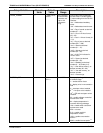
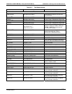
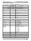
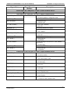
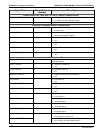
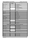
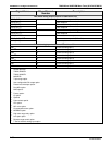
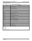
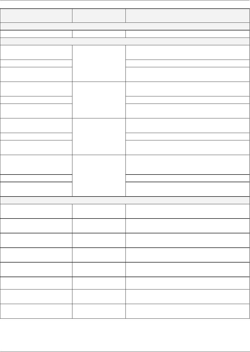
Signal Name Bit or Channel
Number
Description
Control outputs, U21, J1008, pins 9–12 = bits 0–3, default I/O address 325 hex
0–3 Spare
Alarm outputs, U21, J1009, pins 1–12 = bits 4–7, default I/O address 325 hex
ST_SYSTEM_OK2
12
1 = system OK
0 = any alarm condition or in diagnostics mode
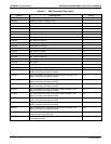
MB_RELAY_36
18
Controlled by MODBUS coil register
OUT_CAL_MODE
13
4
1 = calibration mode
0 = measure mode
ST_CONC_ALARM_1
17
1 = conc. limit 1 exceeded
0 = conc. OK
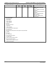
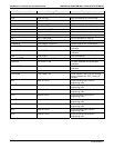
MB_RELAY_37
18
Controlled by MODBUS coil register
OUT_SPAN_CAL
13
5
1 = span calibration
0 = zero calibration
ST_CONC_ALARM_2
17
1 = conc. limit 2 exceeded
0 = conc. OK
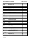
MB_RELAY_38
18
Controlled by MODBUS coil register
OUT_PROBE_1
13
6
0 = select probe #1
1 = not selected
ST_HIGH_RANGE2
19
1 = high auto-range in use (mirrors ST_HIGH_RANGE
status output)
0 = low auto-range
MB_RELAY_39
18
Controlled by MODBUS coil register
OUT_PROBE_2
13
7
0 = select probe #2
1 = not selected
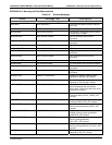
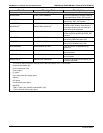
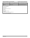
A status outputs, U24, J1017, pins 1–8 = bits 0–7, default I/O address 323 hex
ST_SYSTEM_OK 0 0 = system OK
1 = any alarm condition
ST_CONC_VALID 1 0 = conc. valid
1 = conc. filters contain no data
ST_HIGH_RANGE 2 0 = high auto-range in use
1 = low auto-range
ST_ZERO_CAL 3 0 = in zero calibration
1 = not in zero
ST_SPAN_CAL 4 0 = in span calibration
1 = not in span
ST_DIAG_MODE 5
0 = in diagnostic mode
1 = not in diagnostic mode
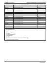
ST_LOW_SPAN_CAL
20
6 0 = in low span calibration
1 = not in low span
ST_O2_CAL
11
7 0 = in O
2
calibration mode
1 = in measure or other calibration mode
07270B DCN6512