


Operating Instructions Teledyne API - Model T200H/T200M Operation Manual
82
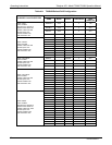
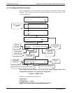
4.7.1.2. DAS Parameters
Data parameters are types of data that may be measured by the analyzers instrumentality
concentrations of measured gases, temperatures of heated zones,, pressures and flows of
the pneumatic subsystem as well as calibration data such as slope and offset for each
gas. For each Teledyne API analyzer model, the list of available data parameters is
different, fully defined and not customizable (see Appendix A for a list of T200H/M
parameters).
Most data parameters have associated measurement units, such as mV, ppm, cm³/min,
etc., although some parameters have no units. The only units that can be changed are
those of the concentration readings according to the SETUP-RANGE settings.
Note The DAS does not keep track of the unit of each concentration value and
DAS data files may contain concentrations in multiple units if the unit was
changed during data acquisition.
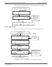
Each data parameter has user-configurable functions that define how the data are
recorded.
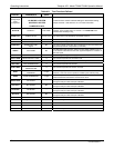
Table 4-8: DAS Data Parameter Functions
FUNCTION EFFECT
PARAMETER
Instrument-specific parameter name.
SAMPLE MODE
INST: Records instantaneous reading.
AVG: Records average reading during reporting interval.
MIN: Records minimum (instantaneous) reading during reporting interval.
MAX: Records maximum (instantaneous) reading during reporting interval.
SDEV: Records the standard deviation of the data points recorded during the reporting
interval.
PRECISION
Decimal precision of parameter value(0-4).
STORE NUM.
SAMPLES
OFF: stores only the average (default).
ON: stores the average and the number of samples in each average for a parameter.
This property is only useful when the AVG sample mode is used. Note that the
number of samples is the same for all parameters in one channel and needs to be
specified only for one of the parameters.
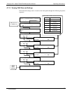
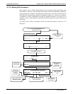
4.7.1.3. DAS Triggering Events
Triggering events define when and how the DAS records a measurement of any given
data channel. Triggering events are firmware-specific and are listed in Appendix A-5.
The most common triggering events are:
ATIMER: Sampling occurs at regular intervals specified by an automatic timer.
Trending information is often stored via such intervals, as either individual datum or
averaged.
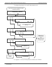
EXITZR, EXITSP, SLPCHG (exit zero, exit span, slope change): Sampling at the
end of an irregularly occurring event such as calibration or when the slope changes.
These events create individual data points. Zero and slope values can be used to
monitor response drift and to document when the instrument was calibrated.
07270B DCN6512