


Principles of Operation Teledyne API - Model T200H/T200M Operation Manual
292
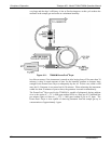
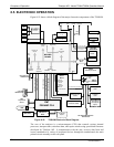
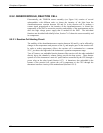
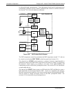
8.5.2. SENSOR MODULE, REACTION CELL
Electronically, the T200H/M sensor assembly (see Figure 9-6) consists of several
subassemblies with different tasks: to detect the intensity of the light from the
chemiluminescence reaction between NO and O
3
in the reaction cell, to produce a
current signal proportional to the intensity of the chemiluminescence, to control the
temperature of the PMT to ensure the accuracy and stability of the measurements and to
drive the high voltage power supply that is needed for the PMT. The individual
functions are described individually below, Section 7.6.5 shows the sensor assembly and
its co
mponents.
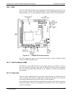
8.5.2.1. Reaction Cell Heating Circuit
The stability of the chemiluminescence reaction between NO and O
3
can be affected by
changes in the temperature and pressure of the O
3
and sample gases in the reaction cell.
In order to reduce temperature effects, the reaction cell is maintained at a constant
50 C, just above the high end of the instrument’s operation temperature range.
Two AC heaters, one embedded into the bottom of the reaction cell, the other embedded
directly above the chamber’s exhaust fitting, provide the heat source. These heaters
operate off of the instrument’s main AC power and are controlled by the CPU through a
power relay on the relay board (Section 8.5.7). A thermistor, also embedded in the
bottom
of the reaction cell, reports the cell’s temperature to the CPU through the
thermistor interface circuitry of the motherboard (Section 8.5.9.3).
07270B DCN6512