


Teledyne API - Model T200H/T200M Operation Manual Operating Instructions
131
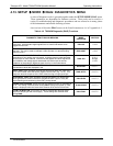
4.13.4. ANALOG OUTPUTS AND REPORTING RANGES
4.13.4.1. Analog Output Signals Available on the T200H/M
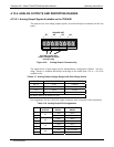
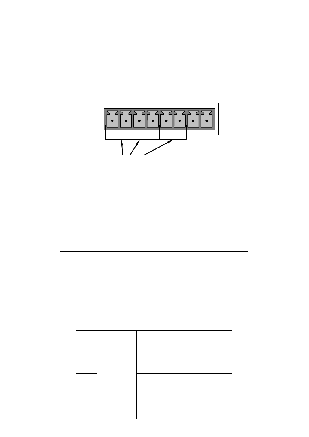
The analyzer has four analog output signals, accessible through a connector on the rear
panel.
ANALOG OUT
A1
A
2
A
3
A
4
+ - + - + - + -
0-20 mA current loop
output available for these
channels only
Figure 4-10: Analog Output Connector Key
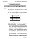
The signal levels of each output can be independently configured as follows. An over-
range feature is available that allows each range to be usable from -5% to + 5% of its
nominal scale:
Table 4-17: Analog Output Voltage Ranges with Over-Range Active
RANGE MINIMUM OUTPUT MAXIMUM OUTPUT
0-0.1 V -5 mV +105 mV
0-1 V -0.05 V +1.05 V
0-5 V -0.25 V +5.25 V
0-10 V -0.5 V +10.5 V
The default offset for all ranges is 0 VDC.
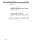
Pin assignments for the ANALOG output connector at the rear panel of the instrument:
Table 4-18: Analog Output Pin Assignments
PIN
ANALOG
OUTPUT
VOLTAGE
SIGNAL
CURRENT
SIGNAL
1 V Out I Out +
2
A1
Ground I Out -
3 V Out I Out +
4
A2
Ground I Out -
5 V Out I Out +
6
A3
Ground I Out -
7 V Out Not Available
8
A4
Ground Not Available
07270B DCN6512