Teledyne API - Model T200H/T200M Operation Manual Table of Contents
xvii
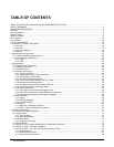
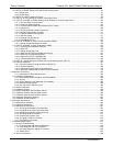
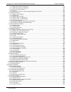
Table 4-18: Analog Output Pin Assignments............................................................................................... 131
Table 4-19: Analog Output Current Loop Range ......................................................................................... 132
Table 4-20: Example of Analog Output Configuration for T200H/M ............................................................ 132
Table 4-21: DIAG - Analog I/O Functions .................................................................................................... 134
Table 4-22: Analog Output Data Type Default Settings............................................................................... 140
Table 4-23: Analog Output DAS Parameters Related to Gas Concentration Data ..................................... 141
Table 4-24: Voltage Tolerances for Analog Output Calibration ................................................................... 151
Table 4-25: Current Loop Output Calibration with Resistor......................................................................... 154
Table 4-26: T200H/M Available Concentration Display Values................................................................... 158
Table 4-27: T200H/M Concentration Display Default Values ...................................................................... 159
Table 4-28: Concentration Alarm Default Settings....................................................................................... 166
Table 4-30: Control Input Pin Assignments ................................................................................................. 168
Table 4-31: Terminal Mode Software Commands ....................................................................................... 170
Table 4-32: Command Types....................................................................................................................... 170
Table 4-33: Serial Interface Documents ...................................................................................................... 176
Table 4-34: RS-232 Communication Parameters for Hessen Protocol ....................................................... 177
Table 6-28: T200H/M Hessen Protocol Response Modes .......................................................................... 178
Table 4-35: T200H/M Hessen GAS ID List.................................................................................................. 180
Table 4-36: Default Hessen Status Bit Assignments ................................................................................... 181
Table 5-1: NIST-SRM's Available for Traceability of NO
x
Calibration Gases ............................................. 185
Table 5-2: AutoCal Modes ......................................................................................................................... 201
Table 5-3: AutoCal Attribute Setup Parameters......................................................................................... 201
Table 5-4: Example Auto-Cal Sequence.................................................................................................... 202
Table 5-5: Calibration Data Quality Evaluation.......................................................................................... 204
Table 6-1: T200H/M Preventive Maintenance Schedule ........................................................................... 206
Table 6-2: Predictive Uses for Test Functions........................................................................................... 207
Table 7-4: Power Configuration for Standard AC Heaters (JP2)............................................................... 243
Table 7-5: Power Configuration for Optional AC Heaters (JP6) ................................................................ 244
Table 7-6: DC Power Test Point and Wiring Color Code........................................................................... 245
Table 7-7: DC Power Supply Acceptable Levels ....................................................................................... 245
Table 7-8: Relay Board Control Devices.................................................................................................... 246
Table 7-9: Analog Output Test Function - Nominal Values ....................................................................... 247
Table 7-10: Status Outputs Pin Assignments ............................................................................................. 248
Table 7-11: Example of HVPS Power Supply Outputs ................................................................................ 252
Table 8-1: List of Interferents ..................................................................................................................... 273
Table 8-2: T200H/M Valve Cycle Phases.................................................................................................. 276
Table 8-3: T200H/M Critical Flow Orifice Diameters and Gas Flow Rates................................................ 280
Table8-4: Thermocouple Configuration Jumper (JP5) Pin-Outs............................................................... 299
Table 8-5: Typical Thermocouple Settings ................................................................................................ 300
Table 9-1: Static Generation Voltages for Typical Activities...................................................................... 312
Table 9-2: Sensitivity of Electronic Devices to Damage by ESD............................................................... 312
LIST OF APPENDICES
APPENDIX A - VERSION SPECIFIC SOFTWARE DOCUMENTATION
APPENDIX B - T200H/M SPARE PARTS LIST
APPENDIX C - REPAIR QUESTIONNAIRE - T200H/M
APPENDIX D - ELECTRONIC SCHEMATICS
07270B DCN6512


