


Teledyne API - Model T200H/T200M Operation Manual Principles of Operation
295
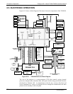
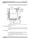
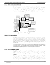
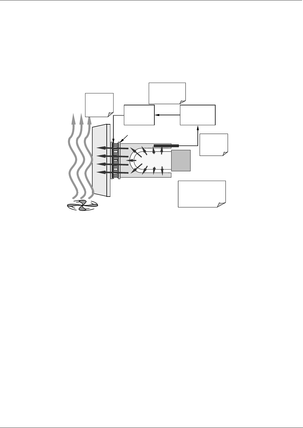
8.5.4. PMT COOLING SYSTEM
The performance of the analyzer’s PMT is significantly affected by temperature.
Variations in PMT temperature are directly reflected in the signal output of the PMT.
Also the signal to noise ratio of the PMT output is radically influenced by temperature
as well. The warmer The PMT is, the noisier its signal becomes until the noise renders
the concentration signal useless. To alleviate this problem a special cooling system
exists that maintains the PMT temperature at a stable, low level
TEC
Control
PCA
PMT Preamp
PCA
Thermistor
outputs temp of
cold block to
preamp PCA
Preamp PCA sends
buffered and
amplified thermistor
signal to TEC PCA
TEC PCA sets
appropriate
drive voltage
for cooler
Heat form PMT is absorbed
by the cold block and
transferred to the heat sink
via the TEC then bled off
into the cool air stream.
PMT
Cold Block
Heat Sink
Cooling Fan
ThermoElectric Cooler
Figure 8-19: PMT Cooling System
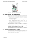
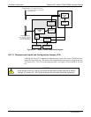
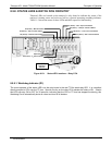
8.5.4.1. TEC Control Board
The TEC control printed circuit assembly is located in the sensor housing assembly,
under the slanted shroud, next to the cooling fins and directly above the cooling fan.
Using the amplified PMT temperature signal from the PMT preamplifier board (see
Section 10.4.5), it sets the drive voltage for the thermoelectric cooler. The warmer the
PMT gets, the more current is passed through the TEC causing it to pump more heat to
the heat sink.
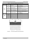
A red LED located on the top edge of this circuit board indicates that the control circuit
is receiving power. Four test points are also located at the top of this assembly. For the
definitions and acceptable signal levels of these test points see Section 11.
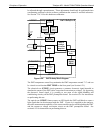
8.5.5. PMT PREAMPLIFIER
The PMT preamplifier board amplifies the PMT signal into a useable analog voltage
(PMT) that can be processed by the motherboard into a digital signal to be used by the
CPU to calculate the NO, NO
2
and NO
x
concentrations of the gas in the sample
chamber.
The output signal of the PMT is controlled by two different adjustments. First, the
voltage across the electron multiplier array of the PMT is adjusted with a set of two
hexadecimal switches. Adjusting this voltage directly affects the HVPS voltage and,
hence, the signal from the PMT. Secondly, the gain of the amplified signal can further
07270B DCN6512