Getting Started Teledyne API - Model T200H/T200M Operation Manual
46
1. Attach a 1/4" exhaust line between the external pump and the EXHAUST port of the
analyzer.
2. Attach an additional 1/4" exhaust port of the pump.
CAUTION
The exhaust from the analyzer must be vented outside the shelter or immediate
area surrounding the instrument and conform to all safety requirements using
a maximum of 10 meters of 1/4” PTFE tubing.
3. Attach a sample inlet line to the SAMPLE inlet port. Ideally, the pressure of the
sample gas should be equal to ambient atmospheric pressure.
Note Maximum pressure of any gas at the SAMPLE inlet should not exceed 1.5
in-Hg above ambient pressure and ideally should equal ambient
atmospheric pressure.
In applications where the sample gas is received from a pressurized
manifold, a vent must be provided to equalize the sample gas with
ambient atmospheric pressure before it enters the analyzer.
The vented gas must be routed outside the immediate area or shelter
surrounding the instrument.
4. Once the appropriate pneumatic connections have been made, check all pneumatic
fittings for leaks using procedures defined in Section 7.5.1.
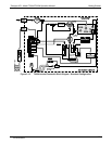
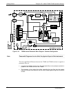
Figure 3-15 and Figure 3-16 show the internal pneumatic flow of the standard
configuration of the T200H and T200M respectively.
07270B DCN6512


