


Troubleshooting & Repair Teledyne API - Model T200H/T200M Operation Manual
258
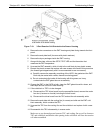
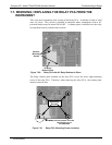
6. Attach the replacement dryer to the mounting bracket in the same orientation as the
old dryer.
7. Fix the dryer to the bracket using new tie wraps.
8. Cut off excess length of the wraps.
9. Put the assembly back into the chassis and tighten the mounting screws.
10. Re-attach the tubes to vacuum manifold, flow meter and/or NO/NO
x
valve using at
least two wrenches.
: Take extra care not to twist the dryer’s white plastic fittings, as this will
result in large leaks that are difficult to trouble-shoot and fix.
11. Carry out a detailed leak check (Section 7.5.2),
12.
Close the analyzer.
13. Power up pump and analyzer and re-calibrate the instrument after it stabilizes.
7.6.4. PMT SENSOR HARDWARE CALIBRATION
The sensor module hardware calibration is used in the factory to adjust the slope and
offset of the PMT output and to optimize the signal output and HVPS. If the
instrument’s slope and offset values are outside of the acceptable range and all other
more obvious causes for this problem have been eliminated, the hardware calibration
can be used to adjust the sensor as has been done in the factory. This procedure is also
recommended after replacing the PMT or the preamplifier board.
1. Perform a full zero calibration using zero air (Section 5.3, 7.4, or 7.6).
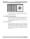
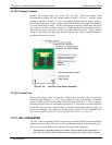
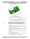
2. On the preamplifier board (located on the sensor housing, Figure 3-5) find the
followin
g components shown in Figure 7-17:
HVPS coarse adjustment switch (Range
0-9, then A-F).
HVPS fine adjustment switch (Range 0-9, then A-F).
Gain adjustment potentiometer (Full scale is 10 turns).
3. Turn the gain adjustment potentiometer 12 turns clockwise to its maximum setting.
4. Feed NO to the analyzer:
For the T200H use 450 ppm NO.
For the T200M use 18 ppm NO.
5. Wait until the STABIL value is below 0.5 ppm
6. Scroll to the NORM PMT value on the analyzer’s front panel.
7. With the NO gas concentrations mentioned instep 5 above, the NORM PMT value
should be 3600 mV.
8. Set the HVPS coarse adjustment to its minimum setting (0). Set the HVPS fine
adjustment switch to its maximum setting (F).
07270B DCN6512