


Principles of Operation Teledyne API - Model T200H/T200M Operation Manual
308
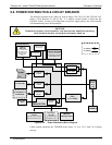
8.8.1. ADAPTIVE FILTER
The T200H/M NO
X
analyzer software processes sample gas concentration data through
a built-in adaptive filter. Unlike other analyzers that average the output signal over a
fixed time period, the T200H/M averages over a defined number of samples, with
samples being about 8 seconds apart (reflecting the switching time of 4 s each for NO
and NO
X
). This technique is known as boxcar filtering. During operation, the software
may automatically switch between two different filters lengths based on the conditions
at hand.
During constant or nearly constant concentrations, the software, by default, computes an
average of the last 42 samples, or approximately 5.6 minutes. This provides smooth and
stable readings and averages out a considerable amount of random noise for an overall
less noisy concentration reading.
If the filter detects rapid changes in concentration the filter reduces the averaging to only
6 samples or about 48 seconds to allow the analyzer to respond more quickly. Two
conditions must be simultaneously met to switch to the short filter. First, the
instantaneous concentration must differ from the average in the long filter by at least 50
ppb. Second, the instantaneous concentration must differ from the average in the long
filter by at least 10% of the average in the long filter.
If necessary, these boxcar filter lengths can be changed between 1 (no averaging) and
1000 samples but with corresponding tradeoffs in rise time and signal-to-noise ratio.
Signal noise increases accordingly when in adaptive filter mode, but remains within the
official T200H/M specifications as long as the filter size remains at or above 3 samples.
In order to avoid frequent switching between the two filter sizes, the analyzer has a
delay of 120 s before switching out of adaptive filter mode, even if the two threshold
conditions are no longer met.
that the filter settings in NO
X
only or NO only
8.8.2. CALIBRATION - SLOPE AND OFFSET
Aside from the hardware calibration of the preamplifier board (Section 13) upon factory
checkout, calibration of the analyzer is usually performed in software. During
instrument calibration (Section 7) the user enters expected values for span gas
concentration through the front panel keypad and supplies the instrument with sample
gas of know NO and NO
X
concentrations. The readings are then compared to the
expected values and the software computes values for the new instrument slope and
offset for both NO and NO
X
response. These values are stored in memory for use in
calculating the NO, NO
X
and NO
2
concentration of the sample gas. By default, the DAS
stores 200 software calibration settings for documentation, review and data analysis.
Instrument slope and offset values recorded during the last calibration can be viewed on
the front panel. NO SLOPE, NOX SLOPE, NO OFFS and NOX OFFS are four of the
test parameters accessible through the <TST TST> buttons.
07270B DCN6512