


Troubleshooting & Repair Teledyne API - Model T200H/T200M Operation Manual
222
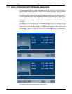
7.1.4. STATUS LED’S
Several color-coded, light-emitting diodes (LED) are located inside the instrument to
determine if the analyzer’s CPU, I
2
C communications bus and the relay board are
functioning properly.
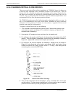
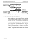
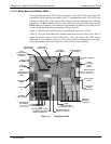
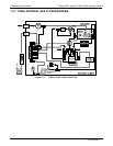
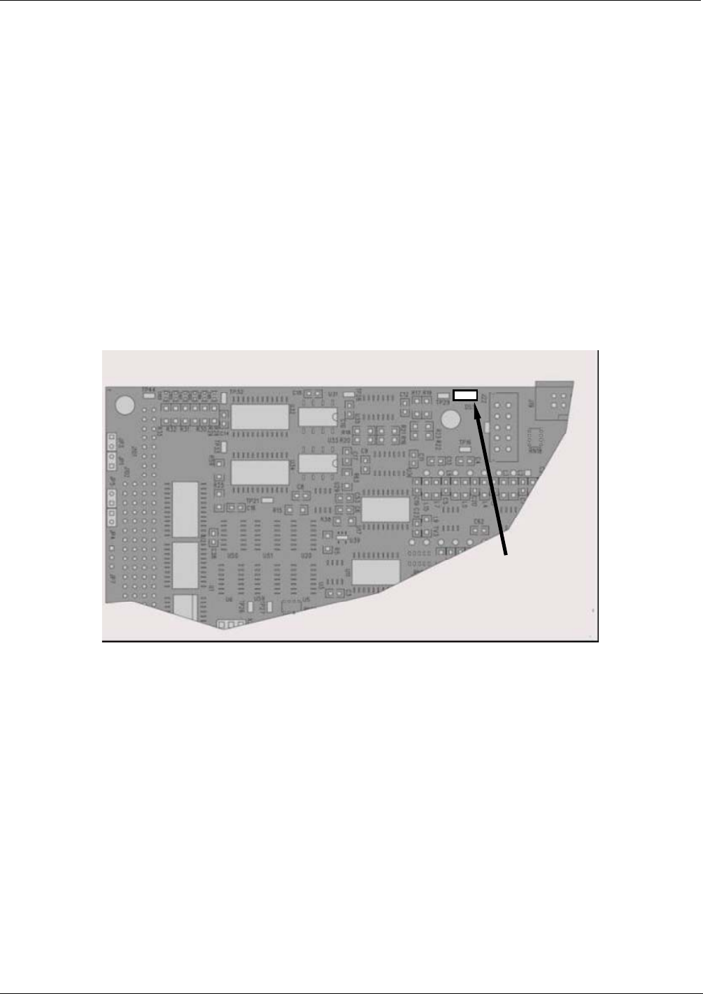
7.1.4.1. Motherboard Status Indicator (Watchdog)
A red LED labeled DS5 in the upper portion of the motherboard (Figure 11-3), just to
the right of the CPU board, flashes when the CPU is running the main program. After
power-up, DS5 should flash on and off about once per second. If characters are visible
on the front panel display but DS5 does not flash then the program files have become
corrupted. Contact Technical Support because it may be possible to recover operation of
the analyzer. If 30 - 60 seconds after a restart neither DS5 is flashing nor any characters
are visible on the front panel display, the firmware may be corrupted or the CPU may be
defective. If DS5 is permanently off or permanently on, the CPU board is likely locked
up and the analyzer should not respond (either with locked-up or dark front panel).
Motherboard
CPU Status LED
Figure 7-3: Motherboard Watchdog Status Indicator
7.1.4.2. CPU Status Indicator
The CPU board has two red LEDs, the lower of which is the watchdog timer (the device
that pulses the motherboard watchdog). This LED is labeled LED2 and blinks about
twice per second (twice as fast as the motherboard LED) when operating normally.
LED1 above LED2 should always be on. However, both CPU LEDs only indicate if the
CPU is powered up properly and generally working. The lower LED can continue to
blink even if the CPU or firmware are locked up.
07270B DCN6512