


Teledyne API - Model T200H/T200M Operation Manual Troubleshooting & Repair
223
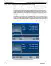
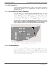
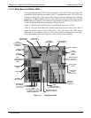
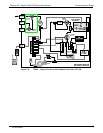
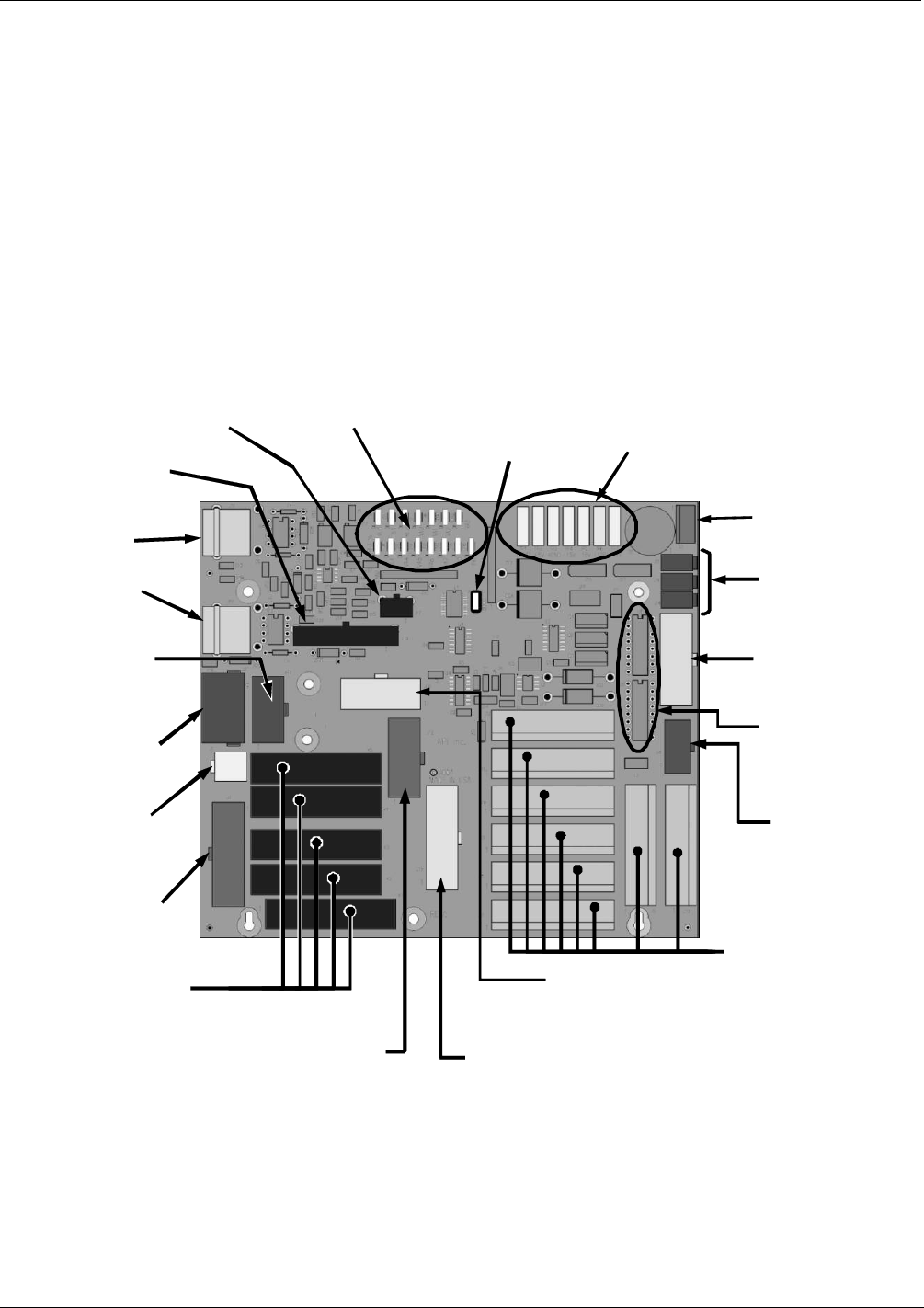
7.1.4.3. Relay Board and Status LEDs
The most important status LED on the relay board is the red I
2
C Bus watch-dog LED,
labeled D1, which indicates the health of the I
2
C communications bus. This LED is the
left-most in LED row 1 in the center of the relay board when looking at the electronic
components. If D1 is blinking, then the other LEDs can be used in conjunction with the
DIAG menu I/O functions to test hardware functionality by manually switching devices
on and off and watching the corresponding LED go on or off.
Figure 7-4 illustrates the relay board layout including the two rows of LEDs,
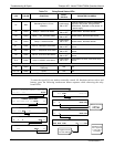
Table 11-2 li
sts the individual LED functions and the menu tree below shows how to
access the manual control of the I/O functions. that only some or the LEDs may be
functional in your analyzer model; the relay board layout is conceptualized for spare,
future functionality and is also common to many of the E-series analyzers.
Power
Connection
for DC
Heaters
Status LED’s
(D2 through D16)
DC Power Supply
Test Points
Watchdog
Status LED (D1)
(JP5)
Thermocouple
Configuration
Jumpers
Thermocouple
Signal Output
I
2
C Connector
Shutter Control
Connector
(T100 Series Only)
V
alve Control
Drivers
Pump Power
Output
(JP7)
Pump AC
Configuration
Jumper
AC Power
IN
AC Heater
Power Output
A
C Power Output for
Optional O
2
sensors
(JP6)
Main AC Heater
Configuration Jumpers
(JP2)
AC Configuration Jumpers
for Optional IZS Valve
Heaters & O
2
Sensors
Solid State AC
Power Relays
(Not Present on
P/N 45230100)
DC Power
Distribution
Connectors
V
alve Option
Control
Connector
(J15)
TC1 Input
(J16)
TC2 Input
Figure 7-4: Relay Board PCA
07270B DCN6512