


Getting Started Teledyne API - Model T200H/T200M Operation Manual
38
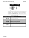
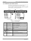
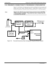
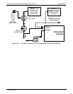
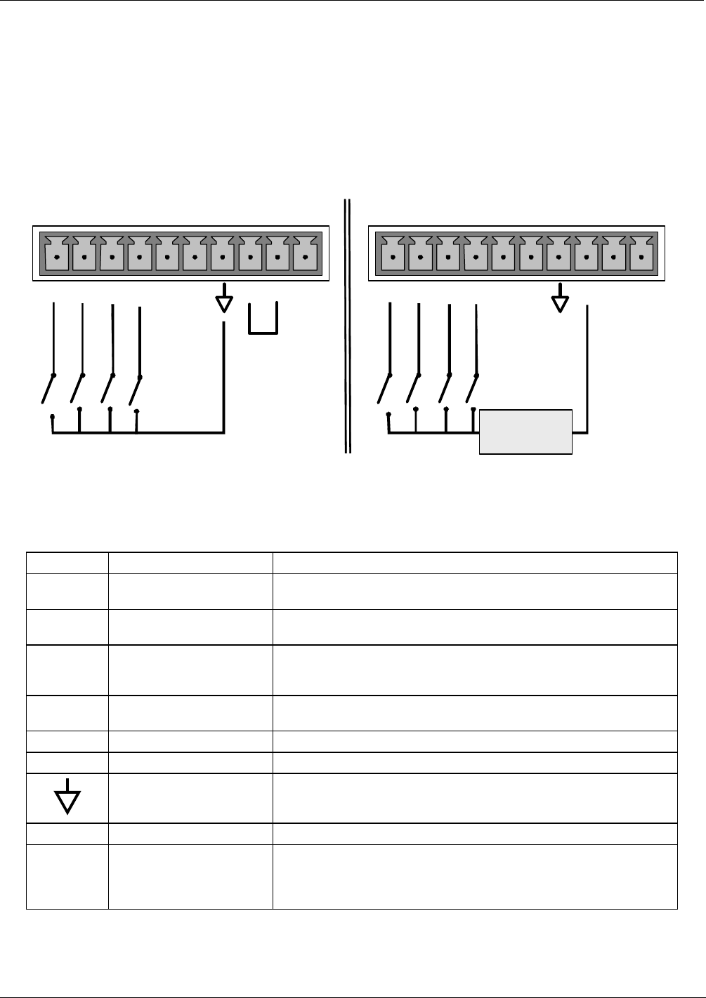
3.4.6. CONNECTING THE CONTROL INPUTS
Control Inputs are used to remotely activate the zero and span calibration modes. Locate
the 10-pin connector labeled CONTROL IN on the analyzer’s rear panel.
There are two methods for energizing the control inputs. The internal +5V available
from the pin labeled “+” is the most convenient method. However, if full isolation is
required, an external 5 VDC power supply should be used.
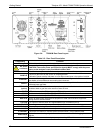
SPAN CAL
ZERO CAL
LOW SPAN
CONTROL IN
Local Power Connections
External Power Connections
SPAN CAL
ZERO CAL
LOW SPAN
CONTROL IN
-
+
5 VDC Power
Supply
A B C D E F U +
A B C D E F U +
RANGE HI
RANGE HI
Figure 3-10: Control Input Connector
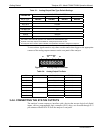
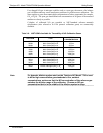
Table 3-6: Control Input Signals
INPUT # STATUS DEFINITION ON CONDITION
A REMOTE ZERO CAL
The analyzer is placed in Zero Calibration mode. The mode field of
the display will read ZERO CAL R.
B REMOTE SPAN CAL
The analyzer is placed in Span Calibration mode. The mode field of
the display will read SPAN CAL R.
C REMOTE LO SPAN CAL
The analyzer is placed in low span calibration mode as part of
performing a low span (midpoint) calibration. The mode field of the
display will read LO CAL R.
D REMOTE RANGE HI
The analyzer is placed into high range when configured for dual
ranges..
E SPARE
F SPARE
Digital Ground
The ground level from the analyzer’s internal DC power supplies
(same as chassis ground).
U External Power input Input pin for +5 VDC required to activate pins A - F.
+ 5 VDC output
Internally generated 5V DC power. To activate inputs A - F, place a
jumper between this pin and the “U” pin. The maximum amperage
through this port is 300 mA (combined with the analog output supply,
if used).
07270B DCN6512