


Teledyne API - Model T200H/T200M Operation Manual Troubleshooting & Repair
245
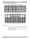
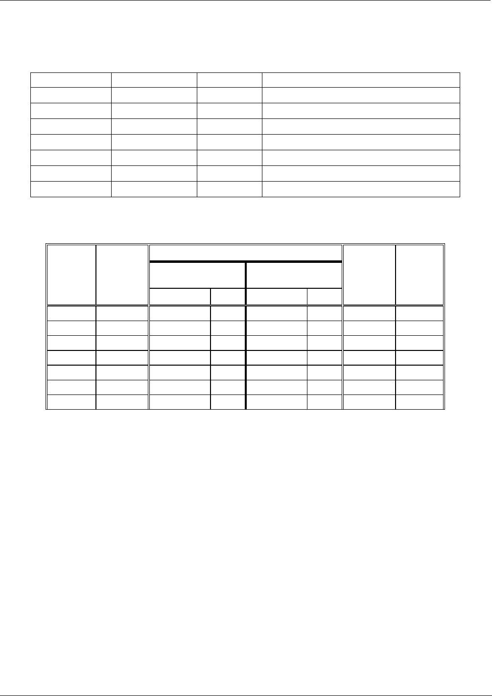
7.5.5. DC POWER SUPPLY TEST POINTS
Table 7-6: DC Power Test Point and Wiring Color Code
NAME TEST POINT# COLOR DEFINITION
DGND
1
Black Digital ground
+5V
2
Red
AGND
3
Green Analog ground
+15V
4
Blue
-15V
5
Yellow
+12R
6
Purple 12 V return (ground) line
+12V
7
Orange
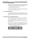
Table 7-7: DC Power Supply Acceptable Levels
CHECK RELAY BOARD TEST POINTS
FROM
Test Point
TO
Test Point
POWER
SUPPLY
VOLTAGE
NAME # NAME #
MIN V MAX V
PS1 +5 DGND 1 +5 2 +4.80 +5.25
PS1 +15 AGND 3 +15 4 +13.5 +16.0
PS1 -15 AGND 3 -15V 5 -14.0 -16.0
PS1 AGND AGND 3 DGND 1 -0.05 +0.05
PS1 Chassis DGND 1 Chassis N/A -0.05 +0.05
PS2 +12 +12V Ret 6 +12V 7 +11.8 +12.5
PS2 DGND +12V Ret 6 DGND 1 -0.05 +0.05
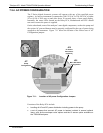
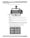
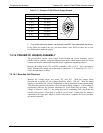
The test points are located at the top, right-hand corner of the PCA (see Figure 7-4)
7.5.6. I
2
C BUS
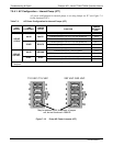
Operation of the I
2
C bus can be verified by observing the behavior of D1 on the relay
PCA & D2 on the Valve Driver PCA . Assuming that the DC power supplies are
operating properly, the I
2
C bus is operating properly if: D1 on the relay PCA and D2 of
the Valve Driver PCA are flashing
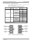
There is a problem with the I
2
C bus if both D1 on the relay PCA and D2 of the Valve
Driver PCA are ON/OFF constantly.
07270B DCN6512