


Teledyne API - Model T200H/T200M Operation Manual Troubleshooting & Repair
243
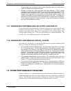
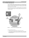
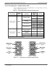
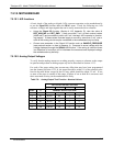
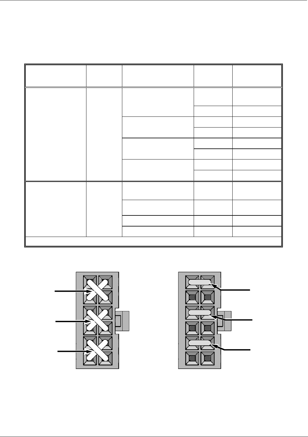
7.5.4.2. AC Configuration – Standard Heaters (JP2)
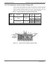
Power configuration for the AC the standard heaters is set using Jumper set JP2 (see
Figure 7-4 for the location of JP2).
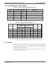
Table 7-4: Power Configuration for Standard AC Heaters (JP2)
LINE VOLTAGE
JUMPER
COLOR
HEATER(S)
JUMPER
BETWEEN
PINS
FUNCTION
1 to 8
Common
Reaction Cell / Sample
Chamber Heaters
2 to 7
Neutral to Load
3 to 10
Common
Mini Hi-Con
Converter
4 to 9
Neutral to Load
3 to 10
Common
Moly Converter
4 to 9
Neutral to Load
5 to 12
Common
110 VAC / 115 VAC
50Hz & 60 Hz
WHITE
Bypass Manifold
1
6 to 11
Neutral to Load
Reaction Cell / Sample
Chamber Heaters
1 to 7
Load
Hi Concentration
Converter
3 to 9
Load
Moly Converter
3 to 9
Load
220 VAC / 240 VAC
50Hz & 60 Hz
BLUE
Bypass Manifold
1
5 to 11
Load
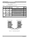
1
Bypass manifold is built into the reaction cell
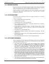
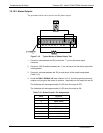
1
2
3
4
5
6
7
8
9
10
11
12
Reaction Cell or
Sample Chamber
Heaters
Mini Hi-Con or
Moly Converter
Heaters
T200M/H
Bypass Manifold
Heater
110 VAC /115 VAC
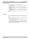
1
2
3
4
5
6
7
8
9
10
11
12
Reaction Cell or
Sample Chamber
Heaters
Mini Hi-Con or
Moly Converter
Heaters
T200H/M
Bypass Manifold
Heater
220 VAC / 240 VAC
Figure 7-13: Typical Set Up of AC Heater Jumper Set (JP2)
07270B DCN6512