


Calibration Procedures Teledyne API - Model T200H/T200M Operation Manual
196
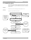
5.5. MANUAL CALIBRATION WITH ZERO/SPAN VALVES
Zero and Span calibrations using the Zero/Span Valve option are similar to that
described in Section 7.2, except that:
Zero air and span gas is supplied to the analyzer through the zero gas and span
gas inlets rather than through the sample inlet.
The zero and cal operations are initiated directly and independently with dedicated
keys (CALZ & CALS)
If both available DAS parameters for a specific gas type are being reported via the
instruments analog outputs e.g. NXCNC1 and NXCNC2, separate calibrations should
be carried out for each parameter.
Use the LOW button when calibrating for NXCNC1
Use the HIGH button when calibrating for NXCNC2.
See Section 4.13.4 for more information on analog output reporting ranges
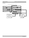
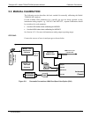
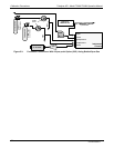
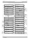
STEP ONE:
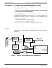
Connect the sources of zero air and span gas to the respective ports on the rear panel as
shown below.
VENT here if input
is pressurized
Source of
SAMPLE Gas
PUMP
Instrument
Chassis
Sample
Exhaust
Span Point
Zero Air
Calibrated NO
at HIGH Span
Concentration
Filter
External Zero
Air Scrubbe
r
VENT if not
vented at
calibrator
MODEL T700
Gas Dilution
Calibrator
MODEL 701
Zero Gas
Generator
Figure 5-4: Pneumatic Connections–With Zero/Span Valve Option (50)
07270B DCN6512