


Teledyne API - Model T200H/T200M Operation Manual Troubleshooting & Repair
251
7.5.13. PMT SENSOR
The photo multiplier tube detects the light emitted by the reaction of NO with ozone. It
has a gain of about 1: 500000 to 1:1000000. It is not possible to test the detector outside
of the instrument in the field. The best way to determine if the PMT is working properly
is by using the optical test (OTEST), which is described in Section 6.13.6.2. The basic
method to diagnose a PMT fault is to eliminate the other components using ETEST,
OTEST and specific tests for other sub-assemblies.
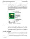
7.5.14. PMT PREAMPLIFIER BOARD
To check the correct operation of the preamplifier board, we suggest to carry out the
optical and electrical tests described in Sections 6.13.6.2 and 4.13.7.3. If the ETEST
fails, the pream
plifier board may be faulty. Refer to Section 13 on hardware calibration
through the pream
plifier board.
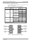
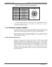
7.5.15. HIGH VOLTAGE POWER SUPPLY
The HVPS is located in the interior of the sensor module and is plugged into the PMT
tube (Section 8.5.2). It requires 2 voltage inputs. The first is +15 V, which powers the
suppl
y. The second is the programming voltage which is generated on the preamplifier
board. Adjustment of the HVPS is covered in the factory calibration procedure in
Section 13. This power supply has 10 independent
power supply steps, one to each pin
of the PMT. The following test procedure below allows you to test each step.
Turn off the instrument.
Remove the cover and disconnect the 2 connectors at the front of the NO
X
sensor
module.
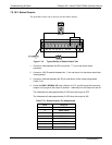
Remove the end cap from the sensor (4 screws).
Remove the HVPS/PMT assembly from the cold block inside the sensor (2 plastic
screws).
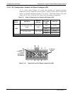
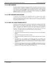
Re-connect the 7 pin connector to the sensor end cap, and power-up the
instrument. Scroll the front panel display to the HVPS test parameter. Divide the
displayed HVPS voltage by 10 and test the pairs of connector points as shown in
Table 11-11.
Check the overall voltage (should be equal to the HVPS value displayed on the front
panel, for example 700 V) and the voltages between each pair of pins of the supply
(should be 1/10
th
of the overall voltage, in this example 70 V):
07270B DCN6512