


Principles of Operation Teledyne API - Model T200H/T200M Operation Manual
286
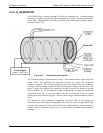
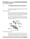
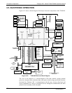
8.3.10. PNEUMATIC SENSORS
Note The T200H/M displays all pressures in inches of mercury absolute (in-Hg-
A), i.e. absolute pressure referenced against zero (a perfect vacuum).
The T200H/M uses three pneumatic sensors to verify gas streams. These sensors are
located on a printed circuit assembly, called the pneumatic pressure/flow sensor board,
located just behind the sensor assembly.
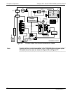
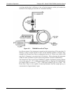
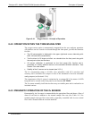
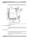
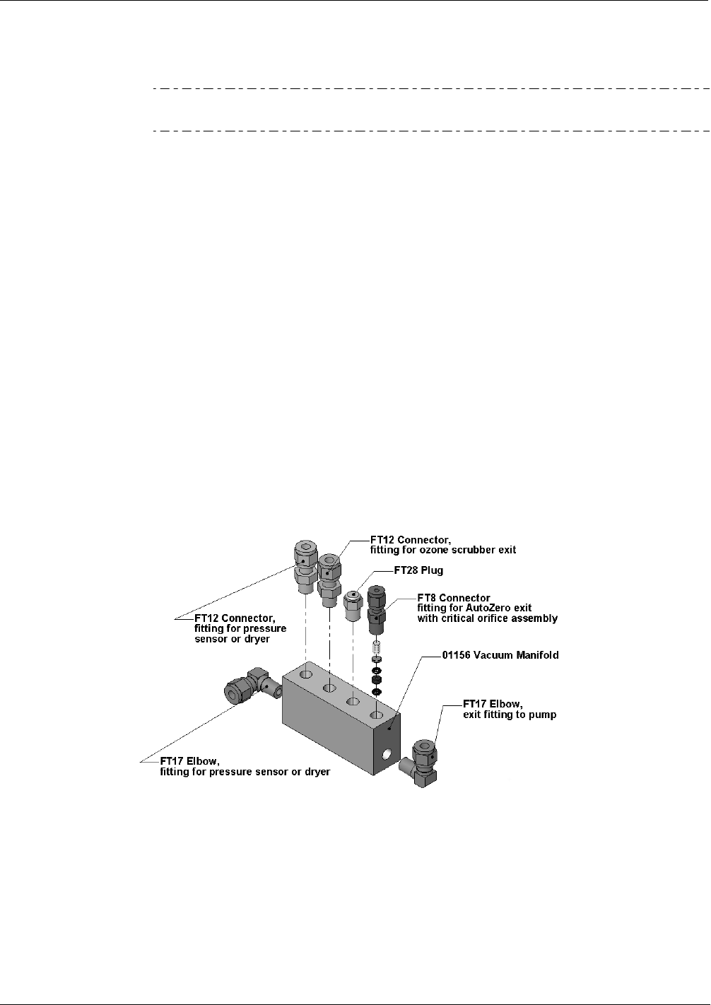
8.3.10.1. Vacuum Manifold
The vacuum manifold is the central exit port for all analyzer pneumatics. All gas
streams of the analyzer exit through this assembly and connect to the instrument’s pump.
Figure 8-12 shows the standard configuration. Configurations will vary
depending on
the optional equipment that is installed. An IZS option, for example, will add another
FT8 connector and orifice assembly to the manifold, an optional sample dryer may add a
Tee-fitting so that two ¼” tubes can be connected to the same port.
At this time, the vacuum manifold does not yet support the orifice holder shown in
Figure 6-5. To exchange the critical orifice install
ed in the vacuum manifold, the user
needs to either blow the orifice out with reversed pressure or remove the entire manifold
for this task. However, orifices installed in the vacuum manifold should not have to be
cleaned under normal circumstances.
Figure 8-12: Vacuum Manifold
8.3.10.2. Sample Pressure Sensor
An absolute pressure transducer connected to the input of the NO/NO
X
valve is used to
measure the pressure of the sample gas before it enters the analyzer’s reaction cell. This
is the “upstream” pressure mentioned above, which is used to compute sample flow rate.
In conjunction with the vacuum pressure sensor, it is also used to validate the critical
flow condition (2:1 pressure ratio) through the sample gas critical flow orifice (Section
07270B DCN6512