


Teledyne API - Model T200H/T200M Operation Manual Operating Instructions
73
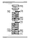
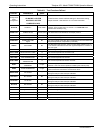
Table 4-1: Analyzer Operating modes
MODE EXPLANATION
SAMPLE
Sampling normally, flashing text indicates adaptive filter is on.
M-P CAL This is the basic calibration mode of the instrument and is activated
by pressing the CAL key.
SETUP X.#
2
SETUP mode is being used to configure the analyzer. The gas
measurement will continue during this process.
SAMPLE A Indicates that unit is in SAMPLE mode and AUTOCAL feature is
activated.
ZERO CAL M
1
Unit is performing ZERO calibration procedure initiated manually by
the user.
ZERO CAL A
1
Unit is performing ZERO calibration procedure initiated automatically
by the AUTOCAL feature.
ZERO CAL R
1
Unit is performing ZERO calibration procedure initiated remotely
through the COM ports or digital control inputs.
LO CAL A Unit is performing LOW SPAN (midpoint) calibration initiated
automatically by the analyzer’s AUTOCAL feature.
LO CAL R Unit is performing LOW SPAN (midpoint) calibration initiated remotely
through the COM ports or digital control inputs.
SPAN CAL M
1
Unit is performing SPAN calibration initiated manually by the user.
SPAN CAL A
1
Unit is performing SPAN calibration initiated automatically by the
analyzer’s AUTOCAL feature.
SPAN CAL R
1
Unit is performing SPAN calibration initiated remotely through the
COM ports or digital control inputs.
DIAG
One of the analyzer’s diagnostic modes is active (Section 4.13).
1
Only Appears on units with Z/S valve or IZS options.
2
The revision of the analyzer firmware is displayed following the word SETUP, e.g., SETUP
F.0.
The very important CAL mode, which allows calibration of the analyzer in various
ways, is described in detail in Section 7.
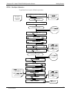
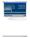
4.2. SAMPLE MODE
This is the analyzer’s standard operating mode. In this mode, the instrument is
analyzing NO and NO
X
and calculating NO
2
concentrations.
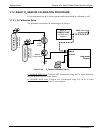
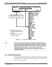
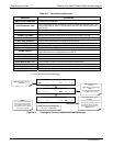
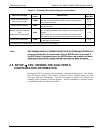
4.2.1. TEST FUNCTIONS
A series of test functions is available at the front panel while the analyzer is in SAMPLE
mode. These parameters provide information about the present operating status of the
instrument and are useful during troubleshooting (Section 7). They can also be recorded
in one of t
he DAS channels (Section 4.7) for data analysis or output on one of the
configurable
analog outputs.
07270B DCN6512