


Teledyne API - Model T200H/T200M Operation Manual Troubleshooting & Repair
231
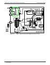
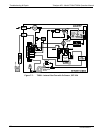
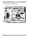
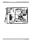
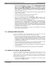
VACUUM
PRESSURE
SENSOR
SAMPLE
PRESSURE
SENSOR
O3 FLOW
SENSOR
PERMAPURE
DRYER
NO/NO
X
VALVE
AUTOZERO
VALVE
REACTION
CELL
PMT
EXHAUST MANIFOLD
NC
COMNO
NC
COM
NO
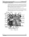
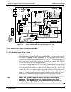
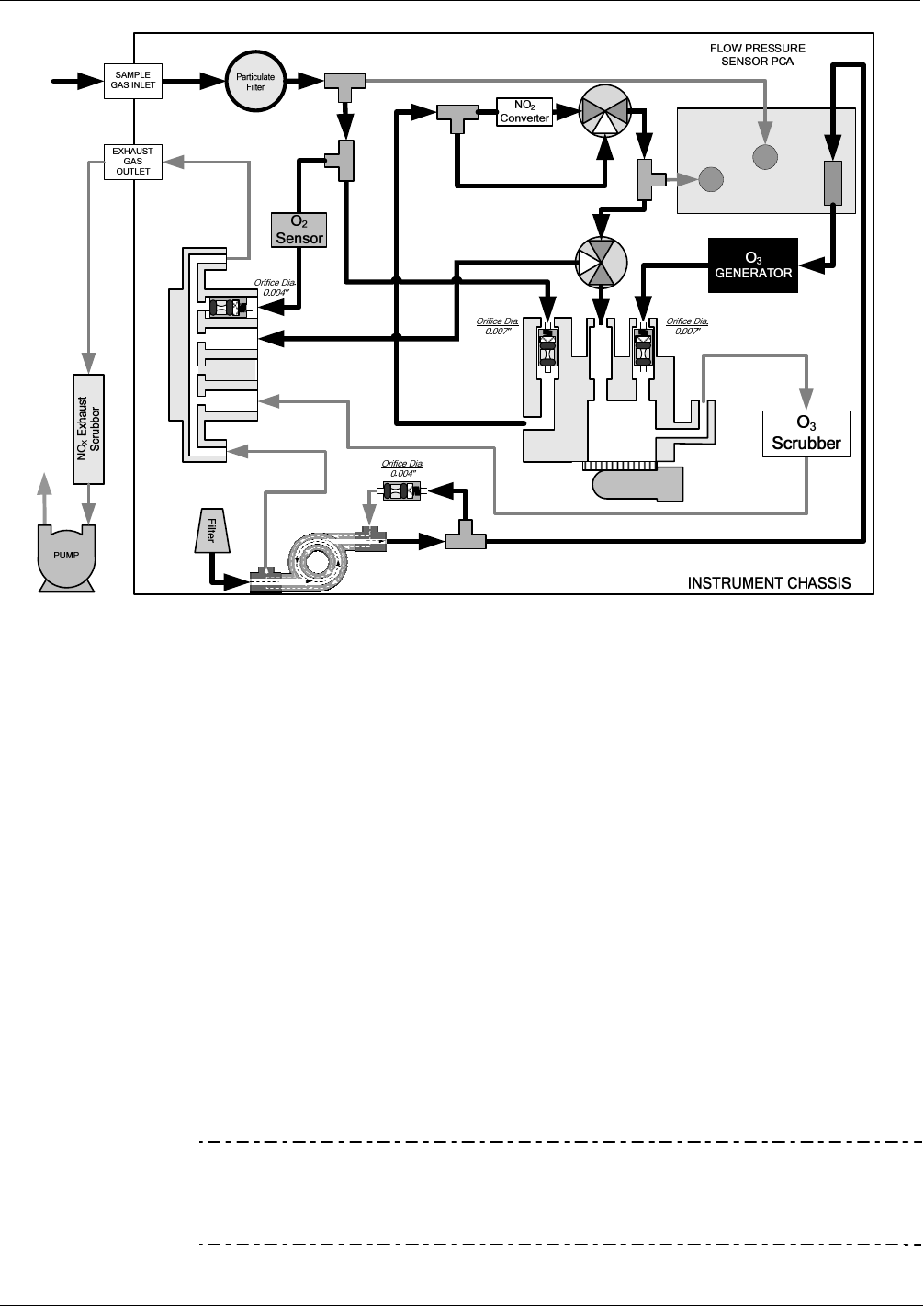
Figure 7-10: T200M – Internal Gas Flow with O
2
Sensor, OPT 65A
7.2.3. ZERO OR LOW FLOW PROBLEMS
7.2.3.1. Sample Flow is Zero or Low
The T200H/M does not actually measure the sample flow but rather calculates it from a
differential pressure between sample and vacuum manifold. On flow failure, the unit
will display a SAMPLE FLOW WARNING on the front panel display and the
respective test function reports XXXX instead of a value “0”. This message applies to
both a flow rate of zero as well as a flow that is outside the standard range (200-600
cm³/min; 300-700 cm³/min with O
2
option installed).
If the analyzer displays XXXX for the sample flow, confirm that the external sample
pump is operating and configured for the proper AC voltage. Whereas the T200H/M
can be internally configured for two different power regimes (100-120 V and 220-240
V, either 50 or 60 Hz), the external pump is physically different for each of three power
regimes (100 V / 50 Hz, 115 V / 60 Hz and 230 V / 50 Hz). If the pump is not running,
use an AC Voltmeter to make sure that the pump is supplied with the proper AC power.
If AC power is supplied properly, but the pump is not running, replace the pump.
Note Sample and vacuum pressures mentioned in this Section refer to
operation of the analyzer at sea level. Pressure values need to be
adjusted for elevated locations, as the ambient pressure decreases by
about 1 in-Hg per 300 m / 1000 ft.
07270B DCN6512