


Principles of Operation Teledyne API - Model T200H/T200M Operation Manual
298
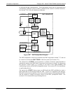
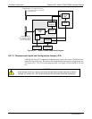
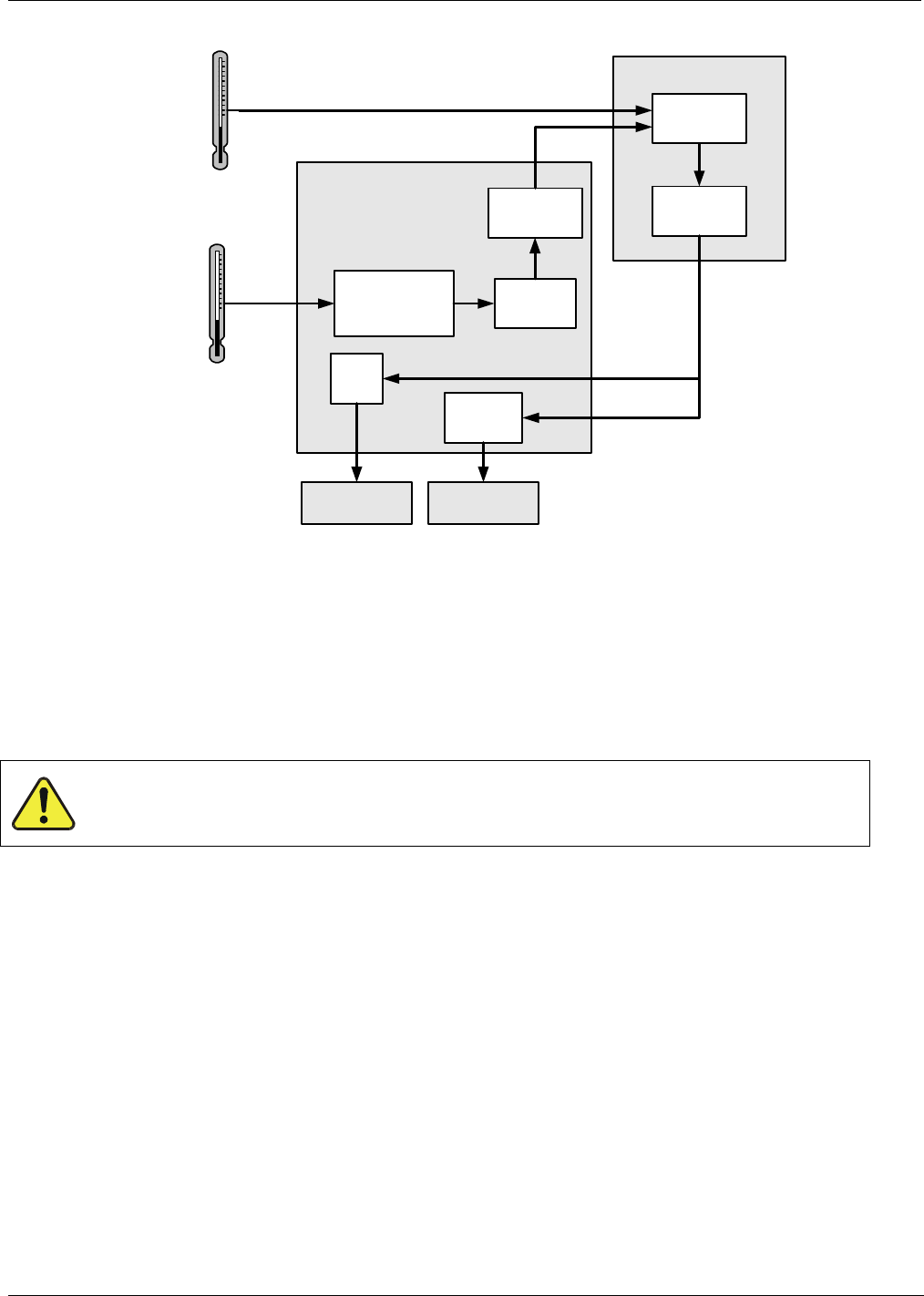
Thermistor(s) – Low Temperature Sensing:
(e.g. Sample Chamber and Reaction
Cell temperatures)
RELAY PCA
DC
Control
Logic
Solid State
AC Relays
Preamplifiers
and Signal
Conditioning
MOTHER BOARD
A/D
Converter
(V/F)
CPU
Themocouple(s)
(High Temperature Sensing;
e.g. Moly and HiCon
Converter temperatures)
AC HEATERSDC HEATERS
THERMOCOUPLE
CONFIGURATION
JUMPER
(JP5)
Cold Junction
Compensation
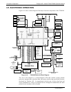
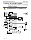
Figure 8-21: Heater Control Loop Block Diagram.
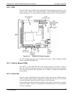
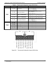
8.5.7.3. Thermocouple Inputs and Configuration Jumper (JP5)
Although the relay PCA supports two thermocouple inputs, the current T200H/M series
analyzers only utilize one. By default, this single thermocouple input is plugged into the
TC1 input (J15). TC2 (J16) is currently not used. See Figure 7-4 for location of J15 and
J16
CAUTION
Avoid damage to the unit: use only the recommended thermocouple type and its specific
settings. If in doubt, call T-API Technical Support for information about the correct part.
07270B DCN6512