


Principles of Operation Teledyne API - Model T200H/T200M Operation Manual
302
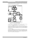
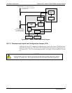
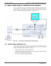
8.5.9. MOTHERBOARD
This is the largest electronic assembly in the analyzer and is mounted to the rear panel as
the base for the CPU board and all I/O connectors. This printed circuit assembly
provides a multitude of functions including A/D conversion, digital input/output, PC-
104 to I
2
C translation, temperature sensor signal processing and is a pass through for the
RS-232 and RS-485 signals.
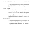
8.5.9.1. A to D Conversion
Analog signals, such as the voltages received from the analyzer’s various sensors, are
converted into digital signals that the CPU can understand and manipulate by the analog
to digital converter (A/D).Under the control of the CPU, this functional block selects a
particular signal input and then coverts the selected voltage into a digital word.
The A/D consists of a voltage-to-frequency (V-F) converter, a programmable logic
device (PLD), three multiplexers, several amplifiers and some other associated devices.
The V-F converter produces a frequency proportional to its input voltage. The PLD
counts the output of the V-F during a specified time period, and sends the result of that
count, in the form of a binary number, to the CPU.
The A/D can be configured for several different input modes and ranges but in the is
used in uni-polar mode with a +5V full scale. The converter includes a 1% over and
under-range. This allows signals from -0.05V to +5.05V to be fully converted.
For calibration purposes, two reference voltages are supplied to the A/D converter:
Reference ground and +4.096 VDC. During calibration, the device measures these two
voltages, outputs their digital equivalent to the CPU. The CPU uses these values to
compute the converter’s offset and slope and uses these factors for subsequent
conversions. See Section 6.13.5.4 for instructions on performing this calibration.
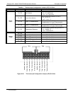
8.5.9.2. Sensor Inputs
The key analog sensor signals are coupled to the A/D converter through the master
multiplexer from two connectors on the motherboard. Terminating resistors (100 kΩ )
on each of the inputs prevent cross-talk between the sensor signals.
PMT DETECTOR OUTPUT: This signal, output by the PMT preamp PCA, is used in
the computation of the NO, NO
2
and NO
x
concentrations displayed at the top right hand
corner of the front panel display and output through the instruments analog outputs and
com ports.
PMT HIGH VOLTAGE POWER SUPPLY LEVEL: This input is based on the drive
voltage output by the PMT pram board to the PMT’s high voltage power supply
(HVPS). It is digitized and sent to the CPU where it is used to calculate the voltage
setting of the HVPS and stored in the instruments memory as the test function HVPS.
HVPS is viewable as a test function (see Section 6.2.1) through the analyzer’s front
panel.
PMT TEMPERATURE: This signal is the output of the thermistor attached to the PMT
cold block amplified by the PMT temperature feedback circuit on the PMT preamp
07270B DCN6512