


Teledyne API - Model T200H/T200M Operation Manual Getting Started
33
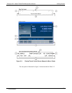
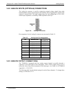
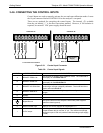
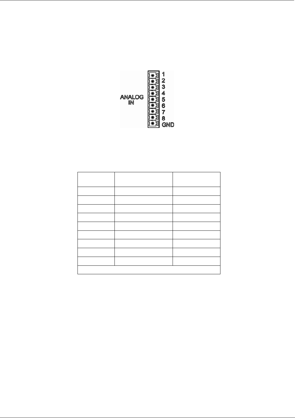
3.4.2. ANALOG INPUTS (OPTION 64) CONNECTIONS
The Analog In connector is used for connecting external voltage signals from other
instrumentation (such as meteorological instruments) and for logging these signals in the
analyzer’s internal DAS. The input voltage range for each analog input is 0-10 VDC,
and the input impedance is nominally 20kΩ in parallel with 0.1µF.
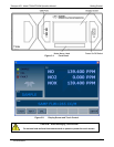
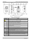
Figure 3-6: Analog In Connector
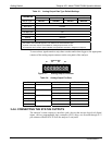
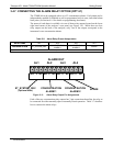
Pin assignments for the Analog In connector are presented in Table 3-3.
Table 3-3: Analog Input Pin Assignments
PIN DESCRIPTION
DAS
PARAMETER
1
1 Analog input # 1 AIN 1
2 Analog input # 2 AIN 2
3 Analog input # 3 AIN 3
4 Analog input # 4 AIN 4
5 Analog input # 5 AIN 5
6 Analog input # 6 AIN 6
7 Analog input # 7 AIN 7
8 Analog input # 8 AIN 8
GND Analog input Ground N/A
1
See Section 4.7 for details on setting up the DAS.
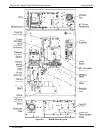
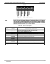
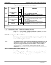
3.4.3. ANALOG OUTPUT CONNECTIONS
The T200H/M is equipped with four analog output channels accessible through a
connector on the back panel of the instrument. Each of these outputs may be set to
reflect the value of any of the instrument’s DAS data types. (see Table A-6 of T200H/M
Appendix A – P/N 05147).
The following table lists the default settings for each of these channels. To change these
settings, see Sections 6.13.4
07270B DCN6512