


Teledyne API - Model T200H/T200M Operation Manual Troubleshooting & Repair
257
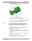
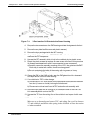
7.6.2. O
3
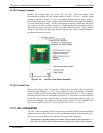
GENERATOR REPLACEMENT
The ozone generator is a black, brick-shaped device with printed circuit board attached
to its rear and two tubes extending out the right side in the front of the analyzer. To
replace the ozone generator:
1. Turn off the analyzer power, remove the power cord and the analyzer cover.
2. Disconnect the 1/8” black tube from the ozone scrubber cartridge and the ¼” clear
tube from the plastic extension tube at the brass fitting nearest to the ozone
generator.
3. Unplug the electrical connection on the rear side of the brick.
4. Unscrew the two mounting screws that attach the ozone generator to the chassis
and take out the entire assembly.
5. If you received a complete replacement generator with circuit board and mounting
bracket attached, simply reverse the above steps to replace the current generator.
6. Make sure to carry out a leak check and a recalibration after the analyzer warmed
up for about 30 minutes.
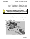
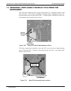
7.6.3. SAMPLE AND OZONE DRYER REPLACEMENT
The T200H/M standard configuration is equipped with a dryer for the ozone supply air.
An optional dryer is available for the sample stream and a combined dryer for both gas
streams can also be purchased. To change one or all of these options:
1. Turn off power to the analyzer and pump, remove the power cord and the analyzer
cover.
2. Locate the dryers in the center of the instrument, between sensor and NO
2
converter.
They are mounted to a bracket, which can be taken out when unscrewing the two
mounting screws (if necessary).
3. Disconnect all tubing that extends out of the dryer assembly,
These are usually the purge tube connecting to the vacuum manifold, the tube from
the exit to the ozone flow meter (ozone dryer) or to the NO/NO
x
valve (sample
dryer) or two tubes to the ozone flow meter and the NO/NO
X
valve (combo-dryer).
Take extra care not to twist any of the white plastic fittings on the dryer, which
connect the inner drying tube to the outer purge tube.
4. the orientation of the dryer on the bracket.
5. Cut the tie wraps that hold the dryer to the mounting bracket and take out the old
dryer.
If necessary, unscrew the two mounting screws on the bracket and take out the
entire assembly.
07270B DCN6512