Teledyne API - Model T200H/T200M Operation Manual Table of Contents
xv
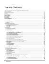
Figure 3-18: Pneumatic Connections–With 2-Span point Option (50D) –Using Bottled Span Gas.................49
Figure 3-19: T200H – Internal Pneumatics with Ambient Zero-Span Valve Option 50A.................................50
Figure 3-20: T200M – Internal Pneumatics with Ambient Zero-Span Valve Option 50A.................................51
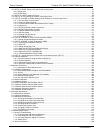
Figure 3-21: T200H - Internal Pneumatics for Zero Scrubber/Dual Pressurized Span, Option 50D ...............55
Figure 3-22: T200M - Internal Pneumatics for Zero Scrubber/Dual Pressurized Span, Option 50D...............56
Figure 3-23: T200H – Internal Pneumatics with O2 Sensor Option 65A .........................................................57
Figure 3-24: T200M – Internal Pneumatics with O
2
Sensor Option 65A..........................................................58
Figure 3-23: O
2
Sensor Calibration Set Up ......................................................................................................66
Figure 4-1: Front Panel Display with “SAMPLE” Indicated in the Mode Field ...............................................72
Figure 4-2: Viewing T200H/M TEST Functions..............................................................................................75
Figure 4-3: Viewing and Clearing T200H/M WARNING Messages...............................................................76
Figure 4-4: APICOM Graphical User Interface for Configuring the DAS .......................................................96
Figure 4-5: Default Pin Assignments for Rear Panel com Port Connectors (RS-232 DCE & DTE) ........... 109
Figure 4-6: CPU COM1 & COM2 Connector Pin-Outs in RS-232 mode.................................................... 110
Figure 4-7: COM – LAN / Internet Manual Configuration............................................................................ 115
Figure 4-8: Jumper and Cables for Multidrop Mode.................................................................................... 120
Figure 4-9: RS-232-Multidrop Host-to-Analyzer Interconnect Diagram ...................................................... 121
Figure 4-10: Analog Output Connector Key.................................................................................................. 131
Figure 4-11: Setup for Calibrating Analog Outputs ....................................................................................... 151
Figure 4-12: Setup for Calibrating Current Outputs ...................................................................................... 153
Figure 4-13: Alternative Setup for Calibrating Current Outputs .................................................................... 154
Figure 4-14. DIAG – Analog Inputs (Option) Configuration Menu ................................................................ 157
Figure 4-15: Status Output Connector .......................................................................................................... 167
Figure 4-16: Control Inputs with local 5 V power supply............................................................................... 169
Figure 4-17: Control Inputs with external 5 V power supply ......................................................................... 169
Figure 4-18: APICOM Remote Control Program Interface ........................................................................... 175
Figure 5-1: Gas Supply Setup for Determination of NO
2
Conversion Efficiency......................................... 187
Figure 5-2: Pneumatic Connections–With Zero/Span Valve Option (50A)................................................. 191
Figure 5-3: Pneumatic Connections–With 2-Span point Option (50D) –Using Bottled Span Gas.............. 192
Figure 5-4: Pneumatic Connections–With Zero/Span Valve Option (50) ................................................... 196
Figure 6-1: Sample Particulate Filter Assembly.......................................................................................... 208
Figure 6-2: Particle Filter on O
3
Supply Air Dryer ....................................................................................... 209
Figure 6-3: NO
2
Converter Assembly.......................................................................................................... 211
Figure 6-4: Reaction Cell Assembly............................................................................................................ 213
Figure 6-5: Critical Flow Orifice Assembly .................................................................................................. 214
Figure 7-1: Viewing and Clearing Warning Messages................................................................................ 219
Figure 7-2: Switching Signal I/O Functions................................................................................................. 221
Figure 7-3: Motherboard Watchdog Status Indicator .................................................................................. 222
Figure 7-4: Relay Board PCA...................................................................................................................... 223
Figure 7-5: T200H – Basic Internal Gas Flow............................................................................................. 226
Figure 7-6: T200H – Internal Gas Flow with Ambient Zero Span, OPT 50A .............................................. 227
Figure 7-7: T200H – Internal Gas Flow with O
2
Sensor, OPT 65A............................................................. 228
Figure 7-8: T200M – Basic Internal Gas Flow............................................................................................. 229
Figure 7-9: T200M – Internal Gas Flow with Ambient Zero Span, OPT 50A.............................................. 230
Figure 7-10: T200M – Internal Gas Flow with O
2
Sensor, OPT 65A ............................................................ 231
Figure 7-11: Location of AC power Configuration Jumpers.......................................................................... 241
Figure 7-12: Pump AC Power Jumpers (JP7)............................................................................................... 242
Figure 7-13: Typical Set Up of AC Heater Jumper Set (JP2) ....................................................................... 243
Figure 7-14: Typical Set Up of AC Heater Jumper Set (JP6) ....................................................................... 244
Figure 7-15: Typical Set Up of Status Output Test ....................................................................................... 248
Figure 7-16: Pressure / Flow Sensor Assembly............................................................................................ 253
Figure 7-17: Pre-Amplifier Board Layout....................................................................................................... 259
Figure 7-18: T200H/M Sensor Assembly ...................................................................................................... 260
Figure 7-19. 3-Port Reaction Cell Oriented to the Sensor Housing.............................................................. 261
Figure 7-20: Relay PCA with AC Relay Retainer In Place............................................................................ 263
Figure 7-21: Relay PCA Mounting Screw Locations.................................................................................... 263
Figure 8-1: T200H/M Sensitivity Spectrum ................................................................................................. 268
Figure 8-2: NO
2
Conversion Principle ......................................................................................................... 269
07270B DCN6512


