


Teledyne API - Model T200H/T200M Operation Manual Troubleshooting & Repair
261
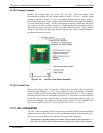
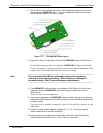
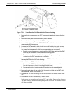
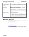
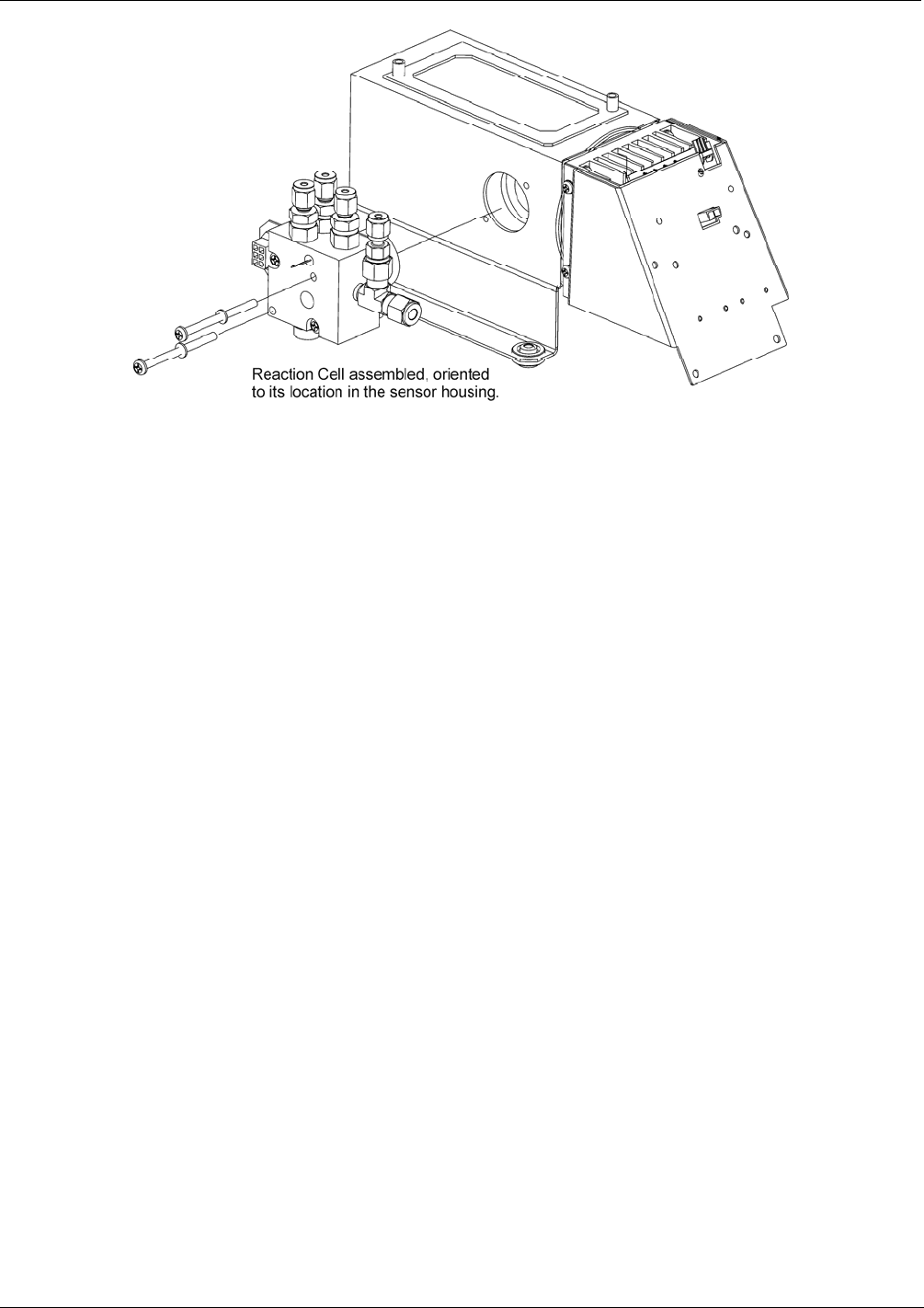
Figure 7-19. 3-Port Reaction Cell Oriented to the Sensor Housing
4. Remove the two connectors on the PMT housing end plate facing towards the front
panel.
5. Remove the end plate itself (4 screws with plastic washers).
6. Remove the dryer packages inside the PMT housing.
7. Along with the plate, slide out the OPTIC TEST LED and the thermistor that
measures the PMT temperature.
8. Unscrew the PMT assembly, which is held to the cold block by two plastic screws.
9. Discard the plastic screws and replace with new screws at the end of this procedure
(the threads get stripped easily and it is recommended to use new screws).
a) Carefully remove the assembly consisting of the HVPS, the gasket and the PMT.
Both may be coated with a white, thermal conducting paste.
b) Do not contaminate the inside of the housing with this grease, as it may
contaminate the PMT glass tube on re-assembly.
10. Change the PMT or the HVPS or both, clean the PMT glass tube with a clean, anti-
static wipe and do not touch it after cleaning.
11. If the cold block or TEC is to be changed:
a) Disconnect the TEC driver board from the preamplifier board, remove the cooler
fan duct (4 screws on its side) including the driver board.
b) Disconnect the driver board from the TEC and set the sub-assembly aside.
12. Remove the end plate with the cooling fins (4 screws) and slide out the PMT cold
block assembly, which contains the TEC.
13. Unscrew the TEC from the cooling fins and the cold block and replace it with a new
unit.
14. Re-assemble this TEC subassembly in reverse order.
Make sure to use thermal grease between TEC and cooling fins as well as between
TEC and cold block and that the side opening in the cold block will face the reaction
cell when assembled.
07270B DCN6512