


Teledyne API - Model T200H/T200M Operation Manual Instrument Maintenance
213
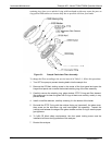
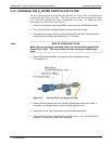
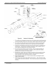
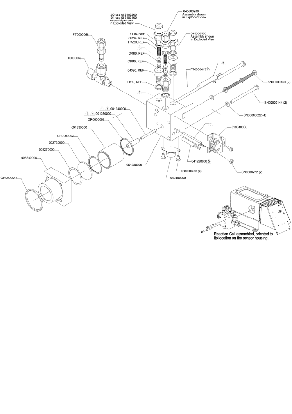
Figure 6-4: Reaction Cell Assembly
1. The reaction cell will separate into two halves, the stainless steel manifold assembly
and the black plastic reaction cell with window, stainless steel cylinder and O-rings.
2. The reaction cell (both plastic part and stainless steel cylinder) and optical glass
filter should be cleaned with methanol and a clean tissue and dried thereafter.
3. Usually it is not necessary to clean the ozone flow orifice since it is protected by a
sintered filter. If tests show that cleaning is necessary, refer to Section 6.3.6 on
how to pe
rform maintenance on the critical flow orifice.
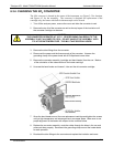
4. Do not remove the sample and ozone nozzles. They are Teflon threaded and
require a special tool for reassembly. If necessary, the manifold with nozzles
attached can be cleaned in an ultrasonic bath.
5. Reassemble in proper order and re-attach the reaction cell to the sensor housing.
Reconnect pneumatics and heater connections, then re-attach the pneumatic
sensor assembly and the cleaning procedure is complete.
6. After cleaning the reaction cell, it is also recommended to exchange the ozone
supply air filter chemical.
7. After cleaning, the analyzer span response may drop 10 - 15% in the first 10 days
as the reaction cell window conditions. This is normal and does not require another
cleaning.
07270B DCN6512