


Teledyne API - Model T200H/T200M Operation Manual Operating Instructions
121
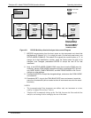
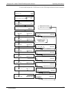
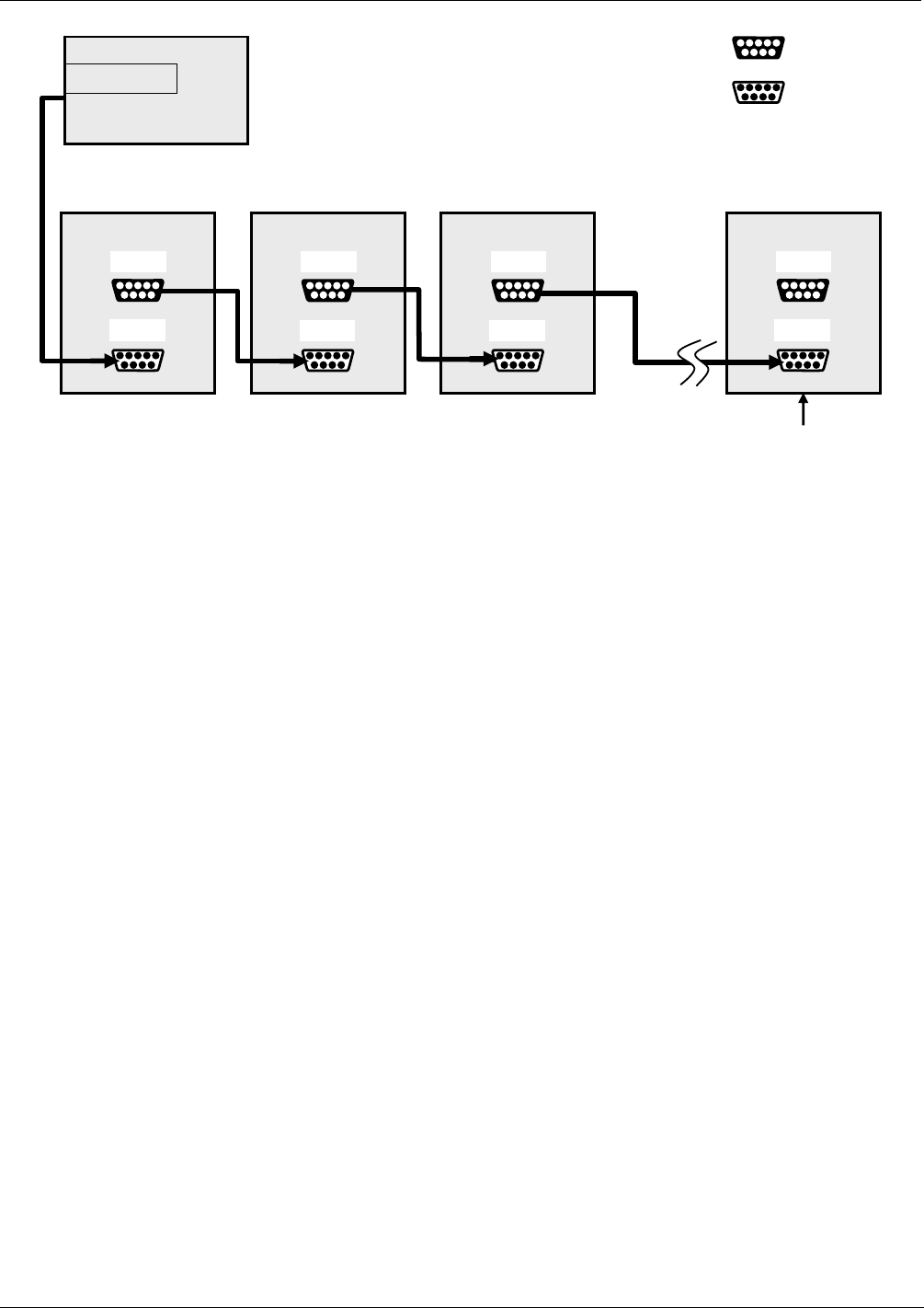
Analyzer Analyzer Analyzer Last Analyzer
Female DB9
Male DB9
RS-232
COM2
RS-232
COM2
RS-232
COM2
RS-232
COM2
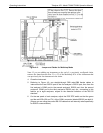
Host
RS-232 port
Ensure jumper is
installed between
JP2 pins 21
22 in
last instrument of
multidrop chain.
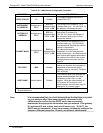
Figure 4-9: RS-232-Multidrop Host-to-Analyzer Interconnect Diagram
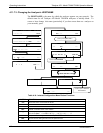
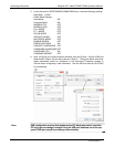
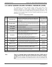
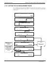
7. BEFORE communicating from the host, power on the instruments and check that
the Machine ID (Section 4.11.1) is unique for each. On the front panel menu, use
SETUP>M
ORE>COMM>ID. The default ID is typically the model number or “0”; to
change the 4-digit identification number, press the button below the digit to be
changed; once changed, press/select ENTER to accept the new ID for that
instrument.
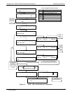
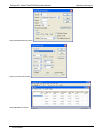
8. Next, in the SETUP>MORE>COMM>COM1 menu (do not use the COM2 menu for
multidrop), edit the COM1 MODE parameter as follows: press/select EDIT and set
only QUIET MODE, COMPUTER MODE, and MULTIDROP MODE to ON. Do not
change any other settings.
9. Press/select ENTER to accept the changed settings, and ensure that COM1 MODE
now shows 35.
10. Press/select SET> to go to the COM1 BAUD RATE menu and ensure it reads the
same for all instruments (edit as needed so that all instruments are set at the same
baud rate).
NOTES:
The (communication) Host instrument can address only one instrument at a time,
each by its unique ID (see Step 7 above).
Teledyne API recommends setting up the first link, between the Host and the first
analyzer, and testing it before setting up the rest of the chain.
07270B DCN6512