


Operating Instructions Teledyne API - Model T200H/T200M Operation Manual
168
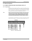
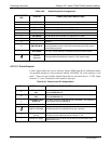
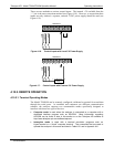
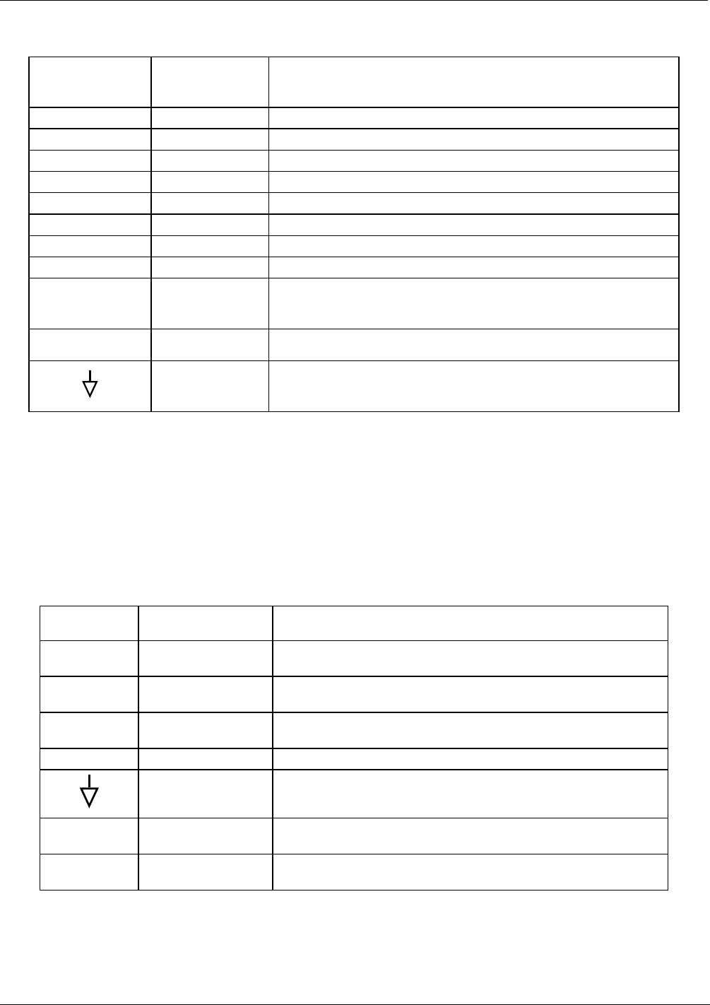
Table 4-29: Status Output Pin Assignments
CONNECTOR
PIN
STATUS CONDITION (ON=CONDUCTING)
1
SYSTEM OK
ON if no faults are present.
2
CONC VALID
ON if concentration measurement is valid, OFF when invalid.
3
HIGH RANGE
ON if unit is in high range of any AUTO range mode.
4
ZERO CAL
ON whenever the instrument is in ZERO calibration mode.
5
SPAN CAL
ON whenever the instrument is in SPAN calibration mode.
6
DIAG MODE
ON whenever the instrument is in DIAGNOSTIC mode.
7
LOW RANGE
ON if unit is in low range of any AUTO range mode.
8
Unused.
D
EMITTER BUS
The emitters of the transistors on pins 1-8 are bussed together. For
most applications, this pin should be connected to the circuit ground
of the receiving device.
+
DC POWER
+ 5 VDC, 30 mA maximum (combined rating with Control Inputs).
DIGITAL
GROUND
The ground from the analyzer’s internal, 5 VDC power supply.
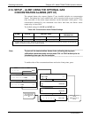
4.15.1.2. Control Inputs
Control inputs allow the user to remotely initiate ZERO and SPAN calibration modes
are provided through a 10-pin connector labeled CONTROL IN on the analyzer’s rear
panel. These are opto-isolated, digital inputs that are activated when a 5 VDC signal
from the “U” pin is connected to the respective input pin.
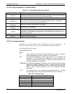
Table 4-30: Control Input Pin Assignments
INPUT STATUS CONDITION WHEN ENABLED
A
EXTERNAL ZERO
CAL
Zero calibration mode is activated. The mode field of the display
will read
ZERO CAL R.
B
EXTERNAL SPAN
CAL
Span calibration mode is activated. The mode field of the display
will read
SPAN CAL R.
C
EXTERNAL LOW
SPAN CAL
Low span (mid-point) calibration mode is activated. The mode field
of the display will read
LO CAL R.
D, E & F
Unused
DIGITAL GROUND Provided to ground an external device (e.g., recorder).
U
DC power for Input
pull ups
Input for +5 VDC required to activate inputs A - F. This voltage can
be taken from an external source or from the “+” pin.
+ Internal +5V Supply
Internal source of +5V which can be used to activate inputs when
connected to pin U.
07270B DCN6512