


Teledyne API - Model T200H/T200M Operation Manual Principles of Operation
305
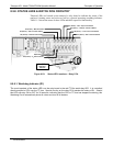
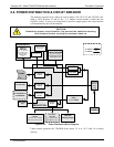
8.6. POWER DISTRIBUTION & CIRCUIT BREAKER
The analyzer operates in two main AC power ranges: 100-120 VAC and 220-240 VAC
(both ± 10%) between 47 and 63 Hz. A 5 ampere circuit breaker is built into the
ON/OFF switch. In case of a wiring fault or incorrect supply power, the circuit breaker
will automatically turn off the analyzer.
CAUTION
Should the power circuit breaker trip correct the condition causing
this situation before turning the analyzer back on.
SENSOR SUITES
LOGIC DEVICES
(e.g. CPU, I
2
C bus,
Touchscreen, Display,
MotherBoard, etc.)
RELAY PCA
ON / OFF
SWITCH
PS 2
(+12 VDC)
OPTIONAL
VALVES
(e.g. Sample/Cal,
Zero/Spans, etc.)
MODEL SPECIFIC
VALVES
(e.g. NO
X
– NO Valves,
Auto-zero valves, etc.)
TEC and
Cooling Fan(s)
PUMP
AC HEATERS
AC HEATERS for
O2 SENSOR
PS 1
ANALOG
SENSORS
(e.g. UV sensors,
Temp Sensors,
Flow Sensors,
PMT HVPS,
etc.)
Pre-Amplifiers
& Amplifiers
Sensor Control
& I/O Logic
Solenoid
Drivers
AC POWER
DC POWER
AC
POWER IN
+5 VDC
±15 VDC
Configuration
Jumpers
Configuration
Jumpers
Configuration
Jumpers
UV Lamp
P/S
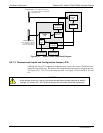
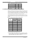
Figure 8-24: Power Distribution Block Diagram
Under normal operation, the T200H/M draws about 1.5 A at 115 V and 2.0 A during
start-up.
07270B DCN6512