


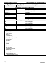
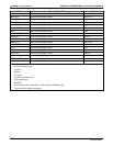


APPENDIX A-7: MODBUS Register Map T200H/M and 200EH/EM Menu Trees (05147H DCN6512)
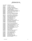
A-38
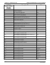
MODBUS
Register Address
(decimal,
0-based)
Description
10
Units
64 Sample pressure “Hg
66 Internal box temperature
C
68 High voltage power supply output Volts
70 Ground reference (REF_GND) mV
72 4096 mV reference (REF_4096_MV) mV
74 Diagnostic test input (TEST_INPUT_13) mV
76 Diagnostic temperature input (TEMP_INPUT_6) °C
78 IZS temperature
C
80
9
Sample restrictor temperature
C
82
9
Remote box temperature
C
80 Diagnostic test input (TEST_INPUT_11) mV
82 Diagnostic temperature input (TEMP_INPUT_5) °C
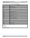
84
1
Raw PMT detector reading for NO
X
mV
86
1
Raw PMT detector reading for NO mV
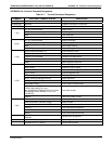
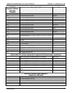
100
3
NO
X
slope for range #3 —
102
3
NO slope for range #3 mV
104
3
NO
X
offset for range #3 mV
106
3
NO offset for range #3 mV
108
3
NO
X
concentration for range #3 during zero/span calibration, just
before computing new slope and offset
PPB
110
3
NO concentration for range #3 during zero/span calibration, just
before computing new slope and offset
PPB
112
3
NO
2
concentration for range #3 during zero/span calibration, just
before computing new slope and offset
PPB
114
3
NO
X
concentration for range #3 PPB
116
3
NO concentration for range #3 PPB
118
3
NO
2
concentration for range #3 PPB
120
3
Converter efficiency factor for range #3 —
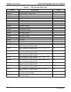
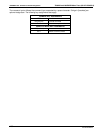
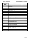
130
12
External analog input 1 value Volts
132
12
External analog input 1 slope eng unit /V
134
12
External analog input 1 offset eng unit
136
12
External analog input 2 value Volts
138
12
External analog input 2 slope eng unit /V
140
12
External analog input 2 offset eng unit
142
12
External analog input 3 value Volts
144
12
External analog input 3 slope eng unit /V
146
12
External analog input 3 offset eng unit
148
12
External analog input 4 value Volts
150
12
External analog input 4 slope eng unit /V
152
12
External analog input 4 offset eng unit
154
12
External analog input 5 value Volts
07270B DCN6512