


Getting Started Teledyne API - Model T200H/T200M Operation Manual
44
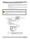
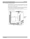
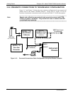
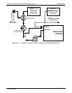
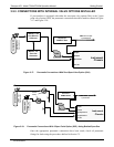
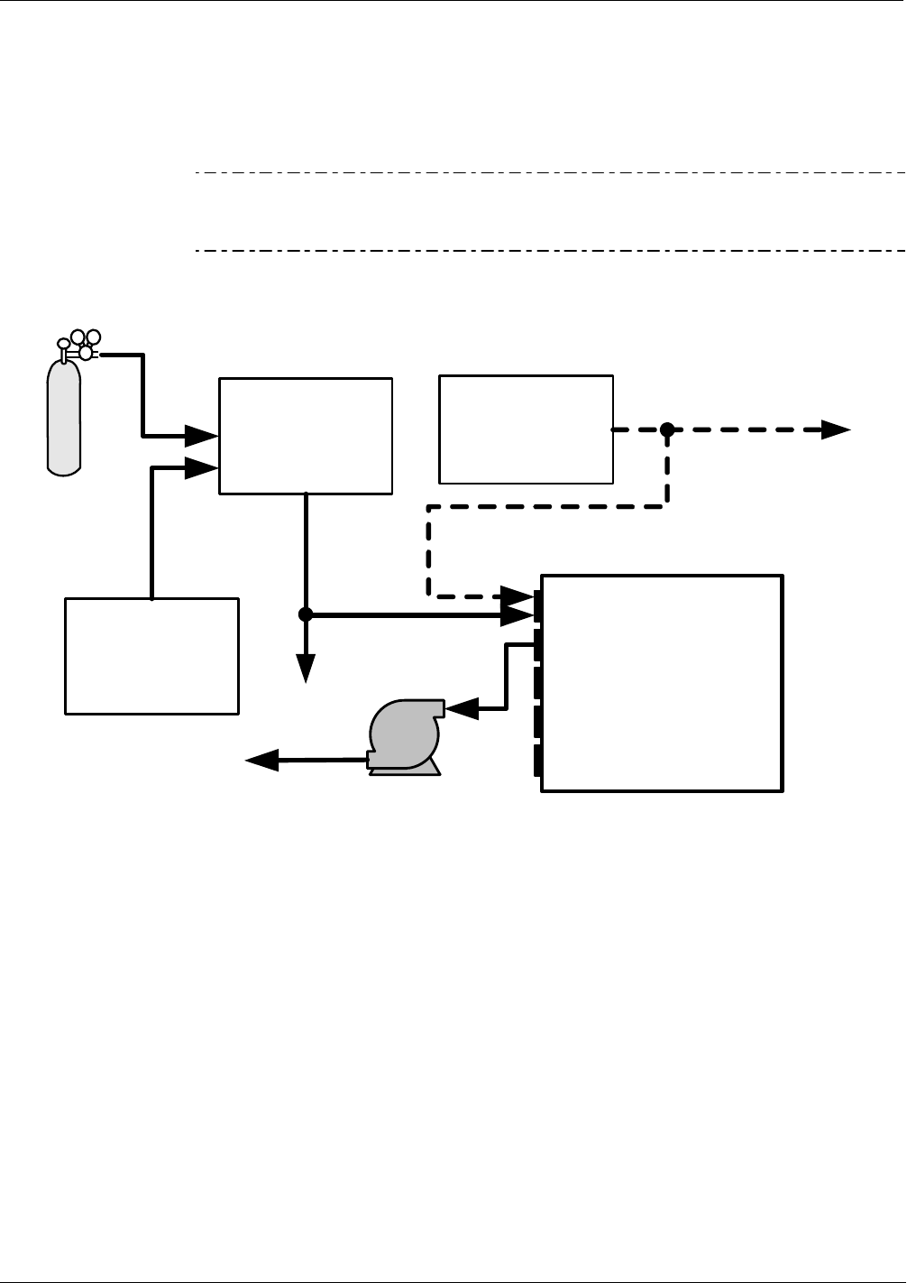
3.5.2. PNEUMATIC CONNECTIONS TO T200H/M BASIC CONFIGURATION
Figure 3-13 and Figure 3-14 show the most common configurations for gas supply and
exhaust lines to the Model T200H/M analyzer. Please refer to Figure 3-4 for the
locations of p
neumatic connections on the rear panel and Table 3-2 for the descriptions.
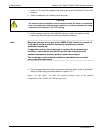
Note
Sample and calibration gases should only come into contact with PTFE
(Teflon) or glass or materials. They should not come in contact with FEP
or stainless steel materials.
Source of
SAMPLE GAS
Removed during
calibration
Instrument
Chassis
SAMPLE
EXHAUST
PUMP
MODEL T700
Gas Dilution
Calibrator
VENT (if no vent
on calibrator)
MODEL 701
Zero Gas
Generator
NO
x
Gas
(High Concentration)
VENT here if input
is pressurized
Figure 3-13: Pneumatic Connections–Basic Configuration–Using Gas Dilution Calibrator
07270B DCN6512