


Getting Started Teledyne API - Model T200H/T200M Operation Manual
60
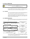
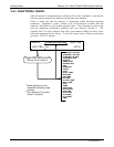
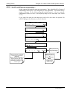
3.6.3. FUNCTIONAL CHECK
After the analyzer’s components have warmed up for at least 30 minutes, verify that the
software properly supports any hardware options that were installed.
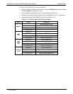
Check to make sure that the analyzer is functioning within allowable operating
parameters. Appendices A and C include a list of test functions viewable from the
analyzer’s front panel as well as their expected values. These functions are also useful
tools for diagnosing performance problems with your analyzer (Section 7). The
enclosed Final Test and
Validation Data Sheet (part number 04490) lists these values
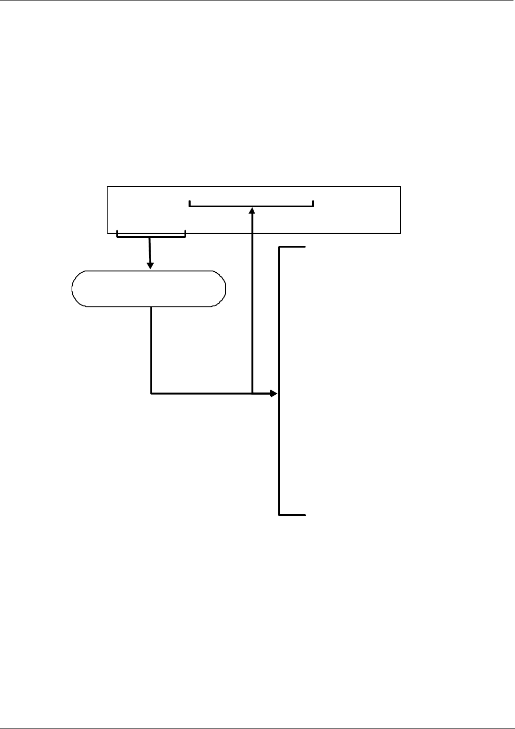
before the instrument left the factory. To view the current values of these test functions
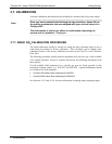
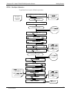
press the <TST TST> buttons:
A
1:NXCNC1=100 PPM
1
A2:N0CNC1=100 PPM
1
A3:N2CNC1=25 PPM
1
A4:NXCNC2=100%
1
NOX STB
SAMP FLOW
OZONE FLOW
PMT
NORM PMT
AZERO
HVPS
RCELL TEMP
BOX TEMP
PMT TEMP
MF TEMP
O2 CELL TEMP
2
MOLY TEMP
RCEL
SAMP
NOX SLOPE
NOX OFFSET
NO SLOPE
NO OFFSET
O2 SLOPE
2
O2 OFFSET
2
TIME
SAMPLE A1:NXCNC1=100 PPM NOX = XXX
< TST TST > CAL SETUP
1
default settings for us er
selectable reporting range
settings.
2
Only appears if O
2
sensor
o
p
tion is installed.
Toggle <TST TST> to scroll
throu
g
h list of functions
07270B DCN6512