


Troubleshooting & Repair Teledyne API - Model T200H/T200M Operation Manual
220
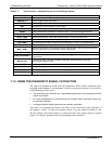
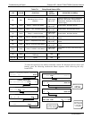
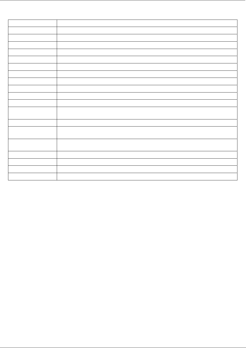
Table 7-1: Test Functions - Possible Causes for Out-Of-Range Values
TEST FUNCTION INDICATED FAILURE(S)
NOX STB
Unstable concentrations; leaks
SAMPLE FL
Leaks; clogged critical flow orifice
OZONE FL
Leaks; clogged critical flow orifice
PMT
Calibration off; HVPS problem; no flow (leaks)
NORM PMT
AutoZero too high
AZERO
Leaks; malfunctioning NO/NOx or AutoZero valve; O
3
air filter cartridge exhausted
HVPS
HVPS broken; calibration off; preamp board circuit problems
RCELL TEMP
Malfunctioning heater; relay board communication (I
2
C bus); relay burnt out
BOX TEMP
Environment out of temperature operating range; broken thermistor
PMT TEMP
TEC cooling circuit broken; relay board communication (I
2
C bus); 12 V power supply
IZS TEMP (OPTION)
Malfunctioning heater; relay board communication (I
2
C bus); relay burnt out
MOLY TEMP
Malfunctioning heater; disconnected or broken thermocouple; relay board communication
(I
2
C bus); relay burnt out; incorrect AC voltage configuration
RCEL (PRESSURE)
Leak; malfunctioning valve; malfunctioning pump; clogged flow orifices
SAMP (PRESSURE)
Leak; malfunctioning valve; malfunctioning pump; clogged flow orifices; sample inlet
overpressure;
NOX SLOPE
HVPS out of range; low-level (hardware) calibration needs adjustment; span gas
concentration incorrect; leaks
NOX OFF
Incorrect span gas concentration; low-level calibration off
NO SLOPE
HVPS out of range; low-level calibration off; span gas concentration incorrect; leaks
NO OFFS
Incorrect span gas concentration; low-level calibration off
TIME OF DAY
Internal clock drifting; move across time zones; daylight savings time?
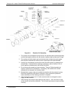
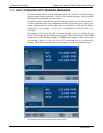
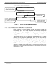
7.1.3. USING THE DIAGNOSTIC SIGNAL I/O FUNCTION
The signal I/O parameters found under the diagnostics (DIAG) menu combined with a
thorough understanding of the instrument’s theory of operation (Section 8) are useful for
troubleshoot
ing in three ways:
The technician can view the raw, unprocessed signal level of the analyzer’s critical
inputs and outputs.
All of the components and functions that are normally under instrument control can
be manually changed.
Analog and digital output signals can be manually controlled.
This allows to systematically observe the effect of these functions on the operation of
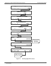
the analyzer. Figure 7-2 shows an example of how to use the
signal I/O menu to view
the raw voltage of an input signal or to control the state of an output voltage or control
signal. The specific parameter will vary depending on the situation.
07270B DCN6512