


Operating Instructions Teledyne API - Model T200H/T200M Operation Manual
78
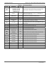
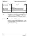
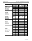
Table 4-5: Secondary Setup Mode Features and Functions
MODE OR FEATURE
KEYPAD
LABEL
DESCRIPTION
MANUAL
SECTION
External Communication
Channel Configuration
COMM
Used to set up and operate the analyzer’s various external I/O
channels including RS-232; RS 485, modem communication
and/or Ethernet access.
6.11 &
6.15
System Status Variables
VARS
Used to view various variables related to the instruments current
operational status
6.12
System Diagnostic Features
and
Analog Output Configuration
DIAG
Used to access a variety of functions that are used to configure,
test or diagnose problems with a variety of the analyzer’s basic
systems.
Most notably, the menus used to configure the output signals
generated by the instruments Analog outputs are located here.
6.13
Alarm Limit Configuration
1
ALRM
Used to turn the instrument’s two alarms on and off as well as
set the trigger limits for each.
6.14
1
Only present if the optional alarm relay outputs (Option 61) are installed.
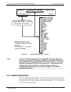
Note Any changes made to a variable during one of the following procedures is
not acknowledged by the instrument until the ENTR button is pressed. If
the EXIT button is pressed before the ENTR button, the analyzer will beep,
alerting the user that the newly entered value has not been accepted.
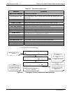
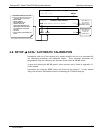
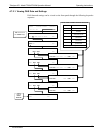
4.5. SETUP CFG: VIEWING THE ANALYZER’S
CONFIGURATION INFORMATION
Pressing the CFG key displays the instrument configuration information. This display
lists the analyzer model, serial number, firmware revision, software library revision,
CPU type and other information. Use this information to identify the software and
hardware when contacting Technical Support. Special instrument or software features
or installed options may also be listed here.
07270B DCN6512