


Teledyne API - Model T200H/T200M Operation Manual Principles of Operation
301
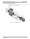
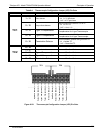
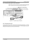
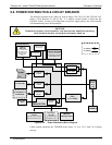
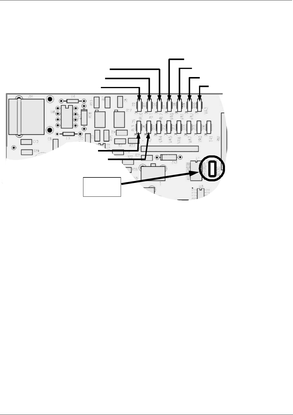
8.5.8. STATUS LEDS & WATCH DOG CIRCUITRY
Thirteen LEDs are located on the analyzer’s relay board to indicate the status of the
analyzer’s heating zones and valves as well as a general operating watchdog indicator.
Table 11-2 shows the states of these LEDs and their respective functionality.
D3 (Yellow) – NO
2
Converter Heater
D4 (Yellow) – Manifold Heater
D2 (Yellow) – Reaction Cell Heater
D5(Yellow)
D6 (Yellow) – O
2
Sensor Heater
D7 (Green)
–
Zero / Span Valve Status
D8 (Green)
–
Sample / Cal Valve Status
D9 (Green )
–
Auto / Zero Valve Status
D10 (Green) – NO
x
/ NO Valve Status
D1 (RED)
Watchdog
Indicator
Figure 8-23: Status LED Locations – Relay PCA
8.5.8.1. Watchdog Indicator (D1)
The most important of the status LED’s on the relay board is the red I
2
C Bus watch-dog LED. It is controlled
directly analyzer’s CPU over the I
2
C bus. Special circuitry on the relay PCA watches the status of D1. Should
this LED ever stay ON or OFF for 30 seconds, indicating that the CPU or I
2
C bus has stopped functioning, this
Watchdog Circuit automatically shuts all valves and turn off all heaters.
07270B DCN6512