iii
This
“Parameter Guide”
contains explanations and other
information regarding the operations of the parameters and
settings on the TRITON STUDIO. The explanations are orga-
nized by mode, and page. Explanations and other informa-
tion on the effects and their parameters are also provided for
each effect.
Refer to this guide when an unfamiliar parameter appears in
the display, or when you need to know more about a partic-
ular function.
Conventions in this manual
References to the TRITON STUDIO
The TRITON STUDIO is available in 88-key, 76-key and 61-
key models, but both models are referred to without distinc-
tion in this manual as “the TRITON STUDIO.” Illustrations
of the front and rear panels in this manual show the 61-key
model, but the illustrations apply equally to the 88-key and
76-key models.
Abbreviations for the manuals BG, PG, VNL
References to the manuals included with the TRITON STU-
DIO are abbreviated as follows in this document.
BG:
Basic Guide
PG:
Parameter Guide
VNL:
Voice Name List
Keys and knobs [ ]
References to the switches, dials, and knobs on the TRITON
STUDIO’s panel are enclosed in square brackets [ ]. Refer-
ences to
buttons
or
tabs
indicate objects in the LCD display
screen.
Parameters in the LCD display screen “ ”
Parameters displayed in the LCD screen are enclosed in
double quotation marks “ ”.
Boldface type
Parameter values are printed in boldface type.
Content that is of particular importance is also printed in
boldface type.
Procedure steps
1
2
3
...
Steps in a procedure are listed as
1
2
3
...
☞
p.
■
,
☞■
–
■
These indicate pages or parameter numbers to which you
can refer.
Symbols , , , , ,
These symbols respectively indicate cautions, advice, MIDI-
related explanations, a parameter that can be selected as an
alternate modulation source, a parameter that can be
selected as a dynamic modulation source, and a parameter
that can use the BPM/MIDI Sync function.
Example screen displays
The values of the parameters shown in the example screens
of this manual are only for explanatory purposes, and may
not necessary match the values that appear in the LCD
screen of your instrument.
MIDI-related explanations
CC#
is an abbreviation for Control Change Number.
In explanations of MIDI messages,
numbers in square
brackets [ ]
always indicate hexadecimal numbers.
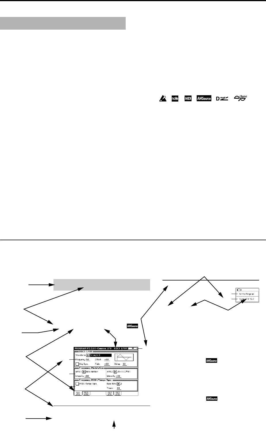
How to read the “Parameter Guide”
(example)
About this manual
Program P5: Edit-Common LFO
5–1: OSC1 LFO1 ( )
5–1
5–1a
5–1b
5–1c
5–1a: OSC1 LFO1
Waveform [Triangle 0…Random6 (Vector)]
Here you can make settings for the LFO that can be used to
cyclically modulate the Pitch, Filter, and Amp of oscillators 1
and 2. There are two LFO units for each oscillator. By setting
the LFO1 or LFO2 Intensity to a negative (–) value for Pitch,
Filter, or Amp, you can invert the LFO waveform.
Make settings for the “OSC1 LFO1,” which is the first LFO
that can be used for oscillator 1.
Select the LFO waveform.
This command exchanges the settings of LFO1 and 2. If LFO2
has been selected as Frequency Modulation AMS1 or 2 of
LFO1, that setting will be cancelled for LFO2 after the LFO1
and 2 settings have been exchanged. If this is selected from
the OSC1 LFO1 or OSC1 LFO2 tab, the LFO1 and LFO2 of
OSC1 will be exchanged.
1 Select this command to open the dialog box.
2 Press the OK button.
5–2: OSC1 LFO2
Here you can make settings for the OSC1 LFO2, which is the
second LFO that can be applied to oscillator 1. (☞“5–1: OSC1
LFO1”) However in “Frequency Modulation” (5–1b), the
LFO cannot be selected as a modulation source in “AMS1” or
“AMS2.”
5–3: OSC2 LFO1
This can be used when “Oscillator Mode” (1–1a) is set to
Double.
Here you can make settings for the OSC2 LFO1, which is the
first LFO that can be applied to oscillator 2. (☞“5–1: OSC1
LFO1”)
Mode name
Page No.
Tab No.
Tab name
Parameter
number
Parameter
name
Page name
Page menu command
Page menu command No.
Page menu
command name
Range of possible
parameter values


