


Appendices
301
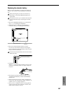
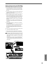
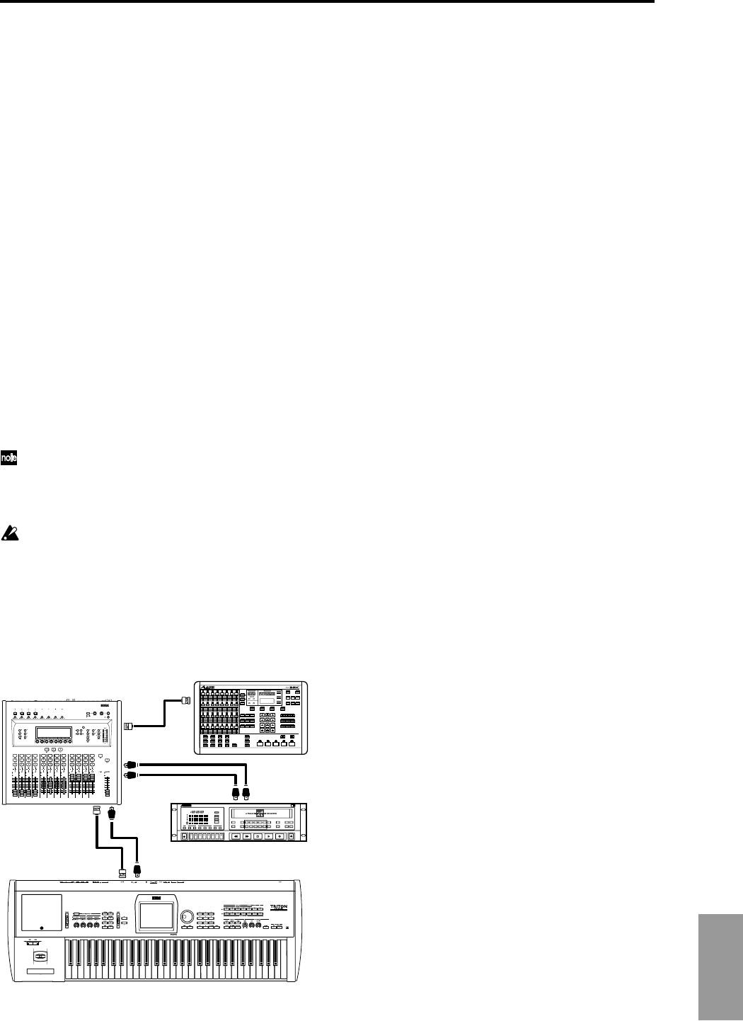
Digitally recording the sound of the TRITON STUDIO
that has been mixed on a digital mixer to the ADAT
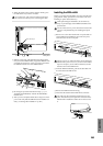
1 Use an ADAT-OPTICAL cable to connect the TRITON
STUDIO’s DIGITAL OUT connector to the ADAT OPTI-
CAL IN connector of the ADAT Optical format-compati-
ble mixer.
2 Use ADAT-OPTICAL cables to connect the respective IN
and OUT connectors of the ADAT Optical format-com-
patible mixer and the ADAT.
3 Make connections as shown in the following diagram so
that an Alesis BRC Remote Controller or other ADAT
optical format compatible mixer or remote controller can
be used as the master for digital signal synchronization,
and connect the WORD CLOCK OUT connector of the
mixer to the WORD CLOCK IN connector of the TRITON
STUDIO.
For connections, use a BNC Coax cable made by Alesis
Corporation or a BNC cable made for video (both sold
separately).
4 Set the TRITON STUDIO’s “System Clock” (Global P0:
0–2a) to Word Clock.
The digital audio signal that is output from the DIGITAL
OUT connector is output in synchronization with the
clock signal received at the WORD CLOCK IN jack,
allowing the digital signals of the two devices to be syn-
chronized.
If you wish to store the “System Clock” setting, use the
“Write Global Setting” utility to write it.
5 Set the word clock source of the ADAT to “DIG 48 K.”
For details refer to the manual for the connected ADAT.
If the clock cannot be detected correctly due to a discon-
nected BNC cable or for some other reason, a error mes-
sage “Word Clock Error!” will appear in the LCD. If this
occurs, check whether a problem has occurred with the
BNC cable.
If “System Clock” has been written as Word Clock, the
same error message will be displayed when the TRI-
TON STUDIO is powered-on if the correct clock is not
being input.
DIGITAL IN
WORD CLOCK OUT
WORD
CLOCK OUT
DIGITAL IN
WORD CLOCK IN
WORD
CLOCK IN
DIGITAL OUT
DIGITAL IN
DIGITAL OUT
DIGITAL OUT
Digital Mixer
ADAT
ADAT BRC
TRITON STUDIO