288
If you have any questions regarding installation, please
contact
your local Korg distributor.
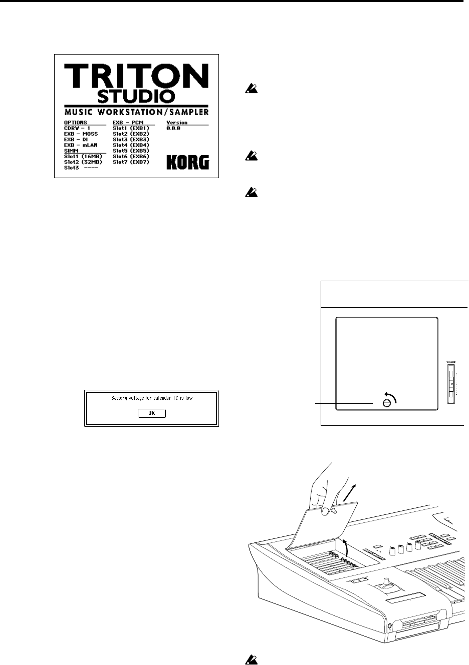
OPTIONS
SIMM
Slot 1...3 (** MB): SIMM’s are installed in SIMM slots 1–3.
The capacity of each SIMM is shown in parentheses. When
shipped from the factory, a 16 MB SIMM is already installed
in SIMM slot 1.
EXB-PCM
Slot 1...7 (****): PCM expansion boards are installed in EXB-
PCM series slots 1–7. The type of each board is shown in
parentheses.
If the calendar battery is not installed correctly, or if the
battery voltage is too low
Installing an EXB-PCM
Before you perform the installation, be sure to read the fore-
going section “Safety precautions” and “Please note when
installing an option board/memory.”
A maximum of seven EXB-PCM boards can be installed
simultaneously.
If you are installing a single EXB-PCM, it will function
correctly when installed in any slot. For easiest installa-
tion, you should use the furthest slot (EXB-PCM Slot 1)
first.
While performing the installation, be careful that you
do not cut your hands on any sharp or pointed edges of
the TRITON STUDIO or the option board.
You must leave the AC power cable disconnected until
you have completed all steps of installing the option
board.
1 Use a coin or similar object to turn the screw counter-
clockwise until the EXB-PCM/sampling memory (RAM)
slot cover (located at the upper left of the front panel) is
released. (Turn the screw counter-clockwise to loosen it,
or clockwise to tighten it.)
2 Raise the EXB-PCM/sample memory (RAM) slot cover
to the angle shown in the diagram, and remove it.
When you open the EXB-PCM/sample memory (RAM)
slot cover, do not raise it too far toward the rear.
3 Remove the EXB-PCM from its packing pouch.
EXB-MOSS:
EXB-DI:
EXB-mLAN:
CDRW-1:
The EXB-MOSS option is installed.
The EXB-DI option is installed.
The EXB-mLAN option is installed
The CDRW-1 option is installed.
EXB-PCM/sample
memory (RAM) slot cover


