


Overview of Operating Modes and Basic Operation Teledyne API – Model T700 Dynamic Dilution Calibrator
110
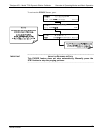
4.2.3.3. Determining the TOTAL FLOW for GPT Calibration Mixtures
The total flow rate is defined by the user depending on system requirements.
The minimum total flow should equal 150% of the flow requirements of all of the
instruments to which the T700 will be supplying calibration gas.
EXAMPLE:
If the T700 is will be expected to supply calibration gas mixtures simultaneously
to a system in composed of three analyzers each requiring 2 LPM, the proper
Total Flow output should be set at:
(2 + 2 + 2) x 1.5 = 9.000 LPM
Note
It is not recommended to set any flow rate to <10% or >100% of the full scale
rating of that associated mass flow controller.
WITH MULTIPLE CALIBRATIONS MASS FLOW CONTROLLERS INSTALLED:
• The full combined flow potential of both mass flow controllers is available to
use with the following limits: The limits are <10% of the lowest rated MFC or
>100% of the combined full-scale ratings for both mass flow controllers.
• The T700 will automatically select the MFC with the lowest flow rate that can
accommodate the requested flow, thereby affording the most precise flow
control.
• If no single MFC can accommodate the requested flow rate, multiple mass flow
controllers are used.
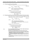
Given this information, the T700 calibrator determines the NO gas flow by the formula:
Equation 4-5
NO
NO
flow
C
TotalflowC
GASNO
×
=
2
WHERE:
C
NO2
= target concentration for the NO
2
output
C
NO
= concentration of the NO gas input
NO GAS
flow
= NO source gas flow rate
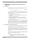
And the diluent (zero air) gas flow by the formula:
Equation 4-6
flow
flowflow
OGASNOTotalflowDIL
3
= - -
WHERE:
GAS
flow
= source gas flow rate (from Equation 6-1)
Totalflow
= total gas flow requirements of the system.
O
3 flow
= the flow rate set for the O
3
generator; a constant value
(typically about 0.105 LPM)
DIL
flow
= required diluent gas flow
06873B DCN6388