


Troubleshooting and Service Teledyne API – Model T700 Dynamic Dilution Calibrator
262
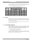
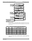
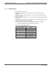
Table 9-14: Control Outputs Pin Assignments and Corresponding Signal I/O Functions Check
PIN (LEFT TO RIGHT) STATUS
1
CONTROL_OUT_1
2
CONTROL_OUT_2
3
CONTROL_OUT_3
4
CONTROL_OUT_4
5
CONTROL_OUT_5
6
CONTROL_OUT_6
7
CONTROL_OUT_7
8
CONTROL_OUT_8
9
CONTROL_OUT_9
10
CONTROL_OUT_10
11
CONTROL_OUT_11
12
CONTROL_OUT_12
9.4.12. CPU
There are two major types of CPU board failures, a complete failure and a failure
associated with the Disk On Module (DOM). If either of these failures occurs, contact
the factory.
For complete failures, assuming that the power supplies are operating properly and the
wiring is intact, the CPU is faulty if on power-on, the watchdog LED on the
motherboard is not flashing.
In some rare circumstances, this failure may be caused by a bad IC on the motherboard,
specifically U57, the large, 44 pin device on the lower right hand side of the board. If
this is true, removing U57 from its socket will allow the instrument to start up but the
measurements will be invalid.
If the analyzer stops during initialization (the front panel display shows a fault or
warning message), it is likely that the DOM, the firmware or the configuration and data
files have been corrupted.
9.4.13. THE CALIBRATOR DOESN’T APPEAR ON THE LAN OR INTERNET
Most problems related to Internet communications via the Ethernet card will be due to
problems external to the calibrator (e.g. bad network wiring or connections, failed
routers, malfunctioning servers, etc.) However, there are several symptoms that indicate
the problem may be with the Ethernet card itself.
If neither of the Ethernet cable’s two status LED’s (located on the back of the cable
connector) is lit while the instrument is connected to a network:
Verify that the instrument is being connected to an active network jack.
Check the internal cable connection between the Ethernet card and the CPU board.
06873B DCN6388