


175
5. COMMUNICATIONS SETUP AND OPERATION
The instrument rear panel connections include an Ethernet port, a USB port (option) and
two serial communications ports (labeled RS232, which is the COM1 port, and COM2)
located on the rear panel (refer to Figure 3-4). These ports give the user the abilit
y to
communicate with, issue commands to, and receive data from the analyzer through an
external computer system or terminal.
This section provides pertinent information regarding communication equipment,
describes the instrument’s communications modes, presents configuration instructions
for the communications ports, and provides instructions for their use.
5.1. DATA TERMINAL/COMMUNICATION EQUIPMENT (DTE DCE)
RS-232 was developed for allowing communications between data terminal equipment
(DTE) and data communication equipment (DCE). Basic terminals always fall into the
DTE category whereas modems are always considered DCE devices. The difference
between the two is the pin assignment of the Data Receive and Data Transmit functions.
• DTE devices receive data on pin 2 and transmit data on pin 3.
• DCE devices receive data on pin 3 and transmit data on pin 2.
To allow the analyzer to be used with terminals (DTE), modems (DCE) and computers
(which can be either), a switch mounted below the serial ports on the rear panel allows
the user to set the RS-232 configuration for one of these two data devices. This switch
exchanges the Receive and Transmit lines on RS-232 emulating a cross-over or null-
modem cable. The switch has no effect on COM2.
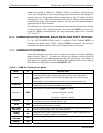
The T700 is equipped with two serial communication ports (labeled RS232 and
COM2), a USB com port and an Ethernet port located on the rear panel. The two serial
ports are accessible via two DB-9 connectors (see Figure 3-4): RS232 (COM1), a male
DB-9 connector, and COM2, a fem
a
le DB9 connector.
The RS232 and COM2 ports operate similarly and give the user the ability to
communicate with, issue commands to, and receive data from the calibrator through an
external computer system or terminal.
The RS-232 port (COM1) can also be configured to operate in single or RS-232
multi-drop mode (option 62, Sections 3.3.1.7 and 5.2).
The COM2 p
ort can be configured for standard RS-232 operation, half-duplex RS-
485 communication. (Contact the factory for RS-485 communication configuration).
The Ethernet connector allows the analyzer to be connected to a network running
TCP/IP or to the public Internet if access is available. The network must have routers
06873B DCN6388