


Teledyne API – Model T700 Dynamic Dilution Calibrator Getting Started
59
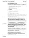
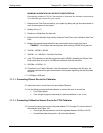
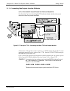
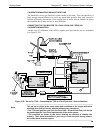
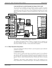
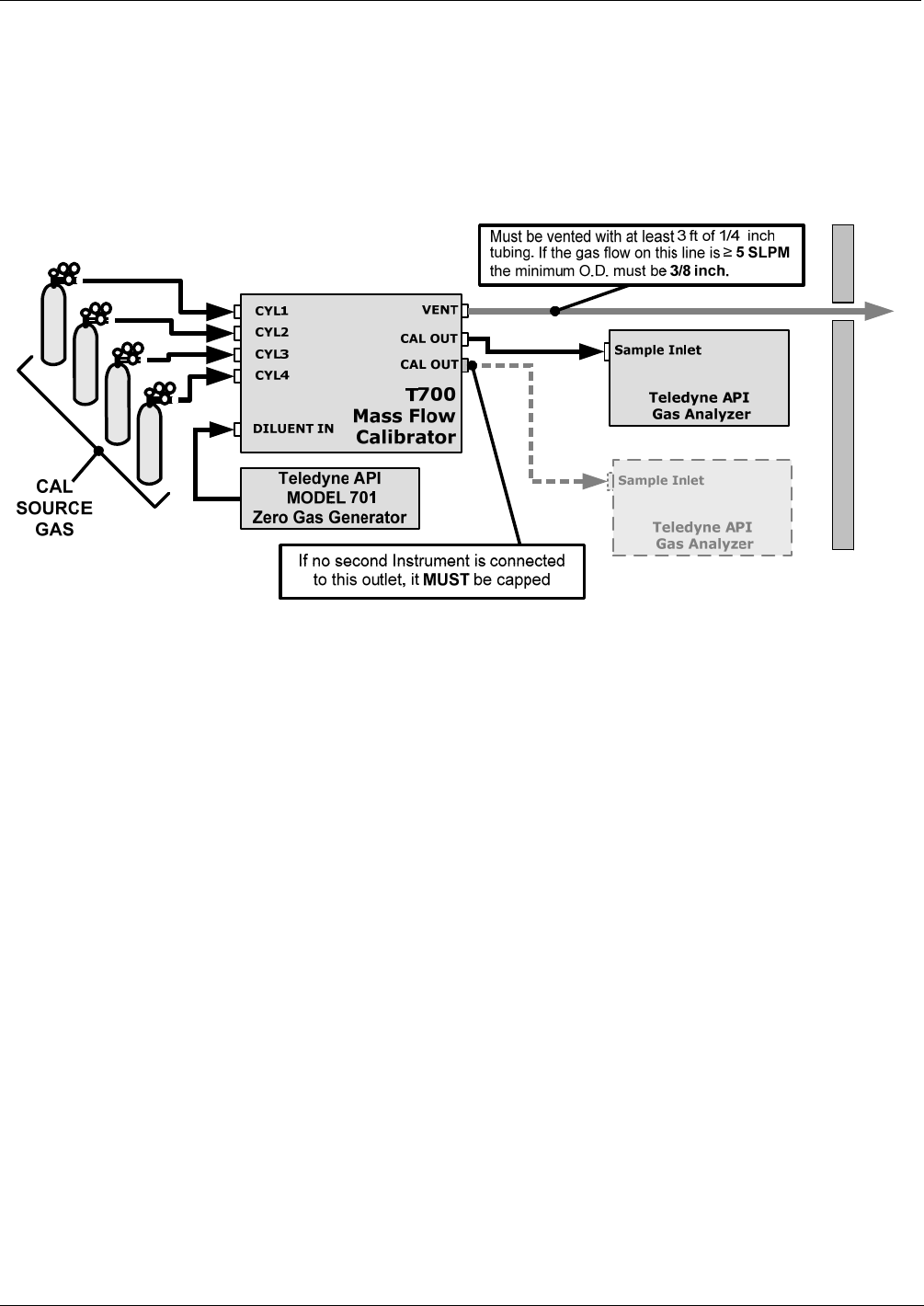
3.3.2.5. Connecting Gas Outputs from the Calibrator
SET UP FOR DIRECT CONNECTIONS TO OTHER INSTRUMENTS
Use this setup if you are connecting the T700 calibrator directly to other instruments
without the use of any shared manifolds.
Enclosure Wall
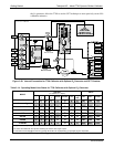
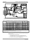
Figure 3-17: Set up for T700 – Connecting the Basic T700 to a Sample Manifold
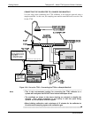
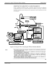
To determine if the gas flow on the vent line is ≥ 5 SLPM subtract the gas flow for each
instrument connected to the outlets of the T700 from the TOTAL FLOW setting for
the calibrator (see Section 3.4.9).
If the T700 has the optional O3 photo
meter installed remember that this option requires
800 cc3/min (0.8 LPM) of additional flow (see Section 3.4.9 or Figure 3-23).
EXAMPLE: Your system has two analyzers each requiring 2SLPM of cal gas flow and
the T700 includes the O
3
photometer. If the TOTAL FLOW rate for the
calibrator is set at 10 SLPM:
10LPM - 2LPM - 2LPM - 0.8 LPM = 5.2LPM
Therefore, the vent would require a gas line with an O.D. 3/8 inch.
06873B DCN6388