


Teledyne API – Model T700 Dynamic Dilution Calibrator Overview of Operating Modes and Basic Operation
111
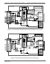
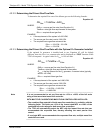
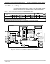
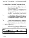
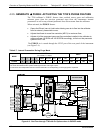
4.2.3.4. T700 Calibrator GPT Operation
The following table and figures show the status of the T700’s internal pneumatic
components and internal gas flow when the instrument is in GPT generating modes.
Table 4-5: Status of Internal Pneumatics During GENERATE GPT Mode
VALVES
(X = Closed; O = Open)
MFCs
MODE
CYL
1
CYL
2
CYL
3
CYL
4
PURGE DILUENT GPT
O
3
GEN
PHOT M/R
CAL1 CAL2
1
DILUENT
PHOT
PUMP
GPT O
2
O
2
O
2
O
2
X O O O
Reference
Phase
ON
3
ON
3
ON OFF
1
Only present if multiple cal gas MFC option is installed.
2
The valve associated with the cylinder containing NO source gas is open.
3
In instrument with multiple MFCs the CPU chooses which MFC to use depending on the target gas flow requested.
Instrument Chassis
PHOTOMETER
PRESSURE SENSOR
O
3
GEN / PHOTOMETER
PRESSURE / FLOW SENSOR PCA
O
3
GAS INPUT
PRESSURE SENSOR
O
3
FLOW
SENSOR
DILUENT
PRESSURE
SENSOR
INPUT GAS
PRESSURE SENSOR
PCA
CAL GAS
PRESSURE
SENSOR
O3 Generator Assembly
O
3
GENERATOR
Flow Control
(1.0 LPM)
Flow Control
(100 cm
3
)
GPT
Valve
O
3
Gen
Valve
REF/MEAS
Valve
On Back Panel
GAS OUTPUT MANIFOLD
PHOTOMETER
OUTLET
CAL GAS
OUTPUT 2
VENT
CAL GAS
OUTPUT 1
DILUENT
INLET
GAS INPUT MANIFOLD
(on back panel)
Purge
Valve
CAL GAS 1
INLET
CAL GAS 3
INLET
CAL GAS 4
INLET
CAL GAS 2
INLET
Cal Gas
Mass Flow Controller 1
Diluent
Mass Flow Controller
GPT
Volume
PHOTOMETER
INLET
EXHAUST
PHOTOMETER
ZERO OUT
PHOTOMETER
ZERO IN
PHOTOMETER BENCH
OFF
Flow Control
(800 cm
3
)
INTERNAL
VENT
Pressure
Regulator
DILUENT
Valve
orn
yel
grn
brn
blk
red
blu
blu
blk
red
gry
wht
vio
vio
grn
brn
brn
orn
yel
yel
yel
gry
wht
ON
ON
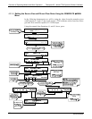
Figure 4-7: Gas Flow through T700 with O
3
Options when in GPT Mode
06873B DCN6388