


Troubleshooting and Service Teledyne API – Model T700 Dynamic Dilution Calibrator
254
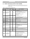
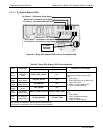
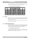
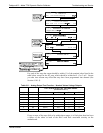
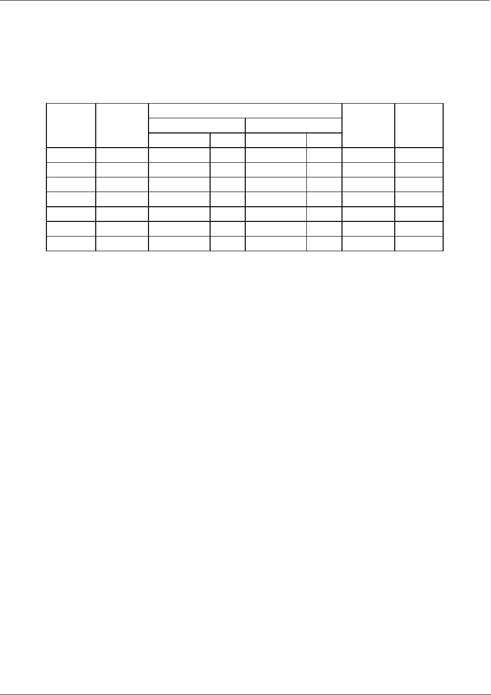
A voltmeter should be used to verify that the DC voltages are correct per the values in
Table 9-9, and an oscilloscope, in AC mode, with band limiting turned on, can be used
to evaluate if the supplies are producing excessive noise (> 100 mV p-p).
Table 9-9: DC Power Supply Acceptable Levels
CHECK RELAY PCA TEST POINTS
FROM TEST POINT TO TEST POINT
POWER
SUPPLY
ASSY
VOLTAGE
NAME # NAME #
MIN V MAX V
PS1 +5 Dgnd 1 +5 2 4.8 5.25
PS1 +15 Agnd 3 +15 4 13.5 16V
PS1 -15 Agnd 3 -15V 5 -14V -16V
PS1 Agnd Agnd 3 Dgnd 1 -0.05 0.05
PS1 Chassis Dgnd 1 Chassis N/A -0.05 0.05
PS2 +12 +12V Ret 6 +12V 7 11.75 12.5
PS2 Dgnd +12V Ret 6 Dgnd 1 -0.05 0.05
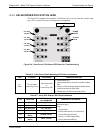
9.4.4. I
2
C BUS
Operation of the I
2
C bus can be verified by observing the behavior of D1 on the relay
PCA & D2 on the Valve Driver PCA. Assuming that the DC power supplies are
operating properly, the I
2
C bus is operating properly if D1 on the relay PCA and D2 of
the Valve Driver PCA are flashing
There is a problem with the I
2
C bus if both D1 on the relay PCA and D2 of the Valve
Driver PCA are ON/OFF constantly.
9.4.5. TOUCHSCREEN INTERFACE
Verify the functioning of the touch screen by observing the display when pressing a
touch-screen control button. Assuming that there are no wiring problems and that the
DC power supplies are operating properly, but pressing a control button on the touch
screen does not change the display, any of the following may be the problem:
The touch-screen controller may be malfunctioning.
The internal USB bus may be malfunctioning.
You can verify this failure by logging on to the instrument using APICOM or a terminal
program. If the analyzer responds to remote commands and the display changes
accordingly, the touch-screen interface may be faulty.
06873B DCN6388