


T700, M700E Calibrator Manuals APPENDIX A-3: Warnings and Test Functions, Revision D.3 (05623D DCN5839)
A-27
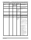
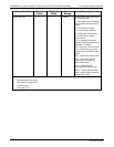
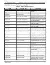
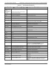
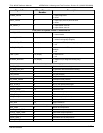
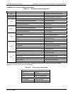
Signal Name Bit or Channel
Number
Description
PURGE_VALVE 5 1 = open purge valve
0 = close
INPUT_VALVE 6 1 = open input (zero-air) shut-off valve
0 = close
DIL_VALVE_2
5
7 1 = open diluent valve #2
0 = open diluent valve #1
Front panel I
2
C keyboard, default I
2
C address 4E hex
MAINT_MODE 5 (input) 0 = maintenance mode
1 = normal mode
LANG2_SELECT 6 (input) 0 = select second language
1 = select first language (English)
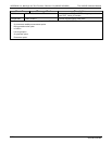
SEQUENCE_LED 8 (output) 0 = sequence LED on (executing sequence)
1 = off
AUTO_TIMER_LED 9 (output)
0 = automatic timer LED on (automatic sequence timer
enabled)
1 = off
FAULT_LED 10 (output) 0 = fault LED on
1 = off
AUDIBLE_BEEPER 14 (output) 0 = beeper on (for diagnostic testing only)
1 = off
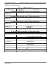
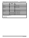
Rear board primary MUX analog inputs
PHOTO_DET 0 Photometer detector reading
O3_GEN_REF_DET 1 O
3
generator reference detector reading
DIL_PRESS 2 Diluent pressure
CAL_PRESS 3 Cal. gas pressure
4 Temperature MUX
O3_PERM_PRESS 5 Ozone/perm tube pressure
6–7 Spare
MFC_FLOW_3
4
8 MFC 3 (cal. gas #2) flow output
REF_4096_MV 9 4.096V reference from MAX6241
PHOTO_FLOW 10 Photometer flow
PHOTO_SAMP_PRES 11 Photometer sample pressure
MFC_FLOW_1 12 MFC 1 (diluent) flow output
MFC_FLOW_2 13 MFC 2 (cal. gas #1) flow output
14 DAC loopback MUX
REF_GND 15 Ground reference
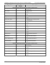
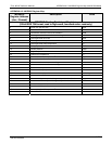
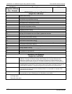
Rear board temperature MUX analog inputs
BOX_TEMP 0 Internal box temperature
PHOTO_SAMP_TEMP 1 Photometer sample temperature
PHOTO_LAMP_TEMP 2 Photometer lamp temperature
O3_GEN_TEMP 3 O
3
generator lamp temperature
PERM_TEMP_1 4 Permeation tube #1 temperature
PERM_TEMP_2
2
5 Permeation tube #2 temperature
06873B DCN6388