


Teledyne API – Model T700 Dynamic Dilution Calibrator Principles of Operation
277
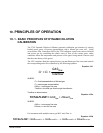
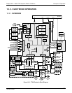
10.2.1. GAS FLOW CONTROL
The precision of gas flow through the T700 Dynamic Dilution Calibrator is centrally
critical to its ability to mix calibration gases accurately. This control is established in
several ways.
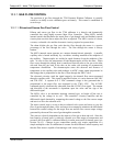
10.2.1.1. Diluent and Source Gas Flow Control
Diluent and source gas flow in the T700 calibrator is a directly and dynamically
controlled buy using highly accurate Mass Flow Controller. These MFCs include
internal sensors that determine the actual flow of gas though each and feedback control
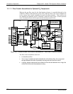
circuitry that uses this data to adjust the flow as required. The MFCs consist of a shunt,
a sensor, a solenoid valve and the electronic circuitry required to operate them.
The shunt divides the gas flow such that the flow through the sensor is a precise
percentage of the flow through the valve. The flow through the sensor is always
laminar.
The MFCs internal sensor operates on a unique thermal-electric principle. A metallic
capillary tube is heated uniformly by a resistance winding attached to the midpoint of
the capillary. Thermocouples are welded at equal distances from the midpoint of the
tube. At zero air flow the temperature of both thermocouples will be the same. When
flow occurs through the tubing, heat is transferred from the tube to the gas on the inlet
side and from the gas back to the tube on the outlet side creating an asymmetrical
temperature distribution. The thermocouples sense this decrease and increase of
temperature in the capillary tube and produces a mVDC output signal proportional to
that change that is proportional to the rate of flow through the MFCs valve.
The electronic circuitry reads the signal output by the thermal flow sensor measured
through a capillary tube. This signal is amplified so that it is varies between 0.00 VDC
and 5.00 VDC. A separate 0 to 5 VDC command voltage is also generated that is
proportional to the target flow rate requested by the T700’s CPU. The 0-5VDC
command signal is electronically subtracted from the 0-5VDC flow signal. The amount
and direction of the movement is dependent upon the value and the sign of the
differential signal.
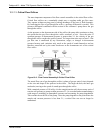
The MFCs valve is an automatic metering solenoid type; its height off the seat is
controlled by the voltage in its coil. The controller’s circuitry amplifies and the
differential signal obtained by comparing the control voltage to the flow sensor output
and uses it to drive the solenoid valve.
The entire control loop is set up so that as solenoid valve opens and closes to vary the
flow of gas through the shunt, valve and sensor in an attempt to minimize the differential
between the control voltage for the target flow rate and the flow sensor output voltage
generated by the actual flow rate of gas through the controller.
This process is heavily dependant on the capacity of the gas to heat and cool. Since the
heat capacity of many gases is relatively constant over wide ranges of temperature and
pressure, the flow meter is calibrated directly in molar mass units for known gases (see
Section 3.4.6.3). Changes in gas composition usually
only require application of a
simple multiplier to the air calibration to account for the difference in heat capacity and
thus the flow meter is capable of measuring a wide variety of gases.
06873B DCN6388