


Getting Started Teledyne API – Model T700 Dynamic Dilution Calibrator
40
3.3. CONNECTIONS AND SETUP
This section presents the electrical (Section 3.3.1) and pneumatic (Section 3.3.2)
connections for setup and preparing for instrument operation.
3.3.1. ELECTRICAL CONNECTIONS
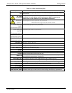
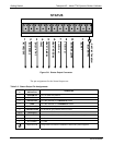
Note To maintain compliance with EMC standards, it is required that the cable
length be no greater than 3 meters for all I/O connections, which include
Analog In, Analog Out, Status Out, Control In, Ethernet/LAN, USB, RS-232,
and RS-485.
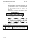
3.3.1.1. Connecting Power
Attach the power cord to the calibrator and plug it into a power outlet capable of
carrying at least 10 A current at your AC voltage and that it is equipped with a
functioning earth ground.
WARNING – ELECTRICAL SHOCK HAZARD
HIGH VOLTAGES ARE PRESENT INSIDE THE CALIBRATORS CASE.
POWER CONNECTION MUST HAVE FUNCTIONING GROUND CONNECTION.
DO NOT DEFEAT THE GROUND WIRE ON POWER PLUG.
TURN OFF CALIBRATOR POWER BEFORE DISCONNECTING OR
CONNECTING ELECTRICAL SUBASSEMBLIES.
DO NOT OPERATE WITH COVER OFF.
CAUTION – AVOID PERSONAL INJURY
DO NOT LOOK AT THE PHOTOMETER UV LAMP; UV LIGHT CAN CAUSE EYE
DAMAGE.
ALWAYS WEAR GLASSES MADE FROM SAFETY UV FILTERING GLASS
(PLASTIC GLASSES ARE INADEQUATE).
Note The T700 calibrator is equipped with a universal power supply that allows
it to accept any AC power configuration, within the limits specified in
Table 2-2.
06873B DCN6388