


Teledyne API – Model T700 Dynamic Dilution Calibrator Calibration and Verification
205
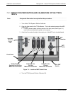
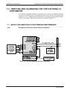
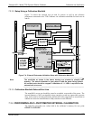
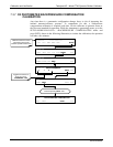
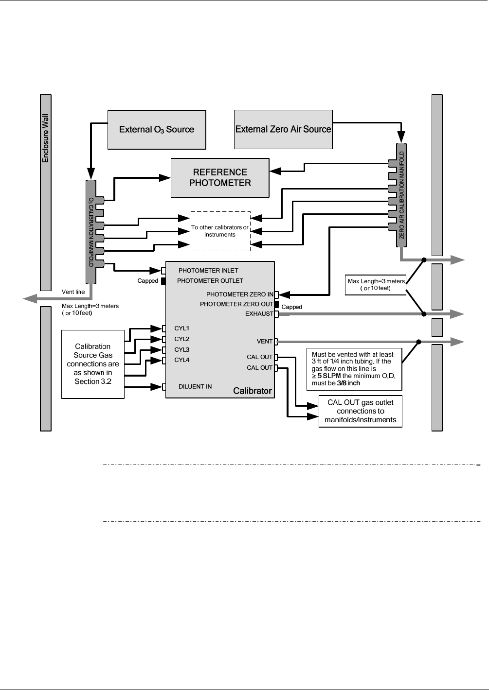
7.3.3.2. Setup Using a Calibration Manifold
Figure 7-4 shows the external zero air and O
3
sources as well as the reference
photometer connected to the T700 Calibrator via calibration manifolds for both zero air
and O
3
.
Figure 7-4: External Photometer Validation Setup with Calibration Manifolds
Note
The manifolds as shown in the above drawing are oriented to simplify the
drawing. The actual orientation in your setup is with the ports facing upward.
All unused ports should be capped. A Minimum of 1.1 LPM is required for the
external zero air source.
7.3.3.3. Calibration Manifold Exhaust/Vent Line
The manifold’s excess gas should be vented to a suitable vent outside of the room. The
internal diameter of this vent should be large enough to avoid any appreciable pressure
drop, and it must be located sufficiently downstream of the output ports to ensure that no
ambient air enters the manifold due to eddy currents or back diffusion.
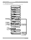
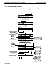
7.3.4. PERFORMING AN O
3
PHOTOMETER EXTERNAL CALIBRATION
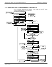
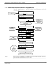
The following procedure sets values held in the calibrator’s memory for zero point
OFFSET and SLOPE.
06873B DCN6388