


Troubleshooting and Service Teledyne API – Model T700 Dynamic Dilution Calibrator
252
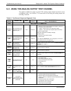
9.4. SUBSYSTEM CHECKOUT
The preceding sections of this manual discussed a variety of methods for identifying
possible sources of failures or performance problems within the T700 calibrator. In
most cases, this included a list of possible components or subsystems that might be the
source of the problem. This section describes how to check individual components or
subsystems to determine if which is actually the cause of the problem being investigated.
9.4.1. VERIFY SUBSYSTEM CALIBRATION
A good first step when troubleshooting the operation of the T700 calibrator is to verify
that its major subsystems are properly calibrated. These are:
The mass flow controllers (see Section 7.2).
Test Channel D A conversion (see Sections 4.10.1.7, 9.4.11.1, and 10.3.5.1).
Gas p
ressure calibration (see Section 7.5).
When optional O
3
components are installed, you should also check:
Photometer calibration (see Section 7.3).
O3 generator calibration (see Section 7.4).
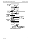
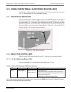
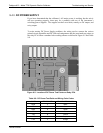
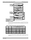
9.4.2. AC MAIN POWER
The T700 calibrator’s electronic systems will operate with any of the specified power
regimes. As long as system is connected to 100-120 VAC or 220-240 VAC at either 50
or 60 Hz it will turn on and after about 30 seconds show a front panel display.
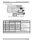
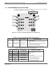
Internally, the status LEDs located on the Relay PCA, Motherboard and CPU should
turn on as soon as the power is supplied.
If they do not, check the circuit breaker built into the ON/OFF switch on the
instruments front panel.
WARNING
SHOULD THE AC POWER CIRCUIT BREAKER TRIP, INVESTIGATE AND CORRECT
THE CONDITION CAUSING THIS SITUATION BEFORE TURNING THE
CALIBRATOR BACK ON.
06873B DCN6388