


Teledyne API – Model T700 Dynamic Dilution Calibrator Principles of Operation
285
WARNING
NEVER REMOVE THIS SAFETY SHIELD WHILE THE INSTRUMENT IS PLUGGED
IN AND TURNED ON. THE CONTACTS OF THE AC RELAY SOCKETS BENEATH
THE SHIELD CARRY HIGH AC VOLTAGES EVEN WHEN NO RELAYS ARE
PRESENT
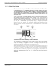
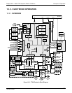
10.3.3.1. Valve Control
The relay PCA also hosts two valve driver chips, each of which can drive up four valves.
In the T700, the relay PCA controls only those valves associated with the O
3
generator
and photometer options. All valves related to source gas and diluent gas flow are
controlled by a separate valve driver PCA (see Section 10.3.4).
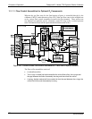
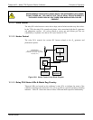
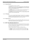
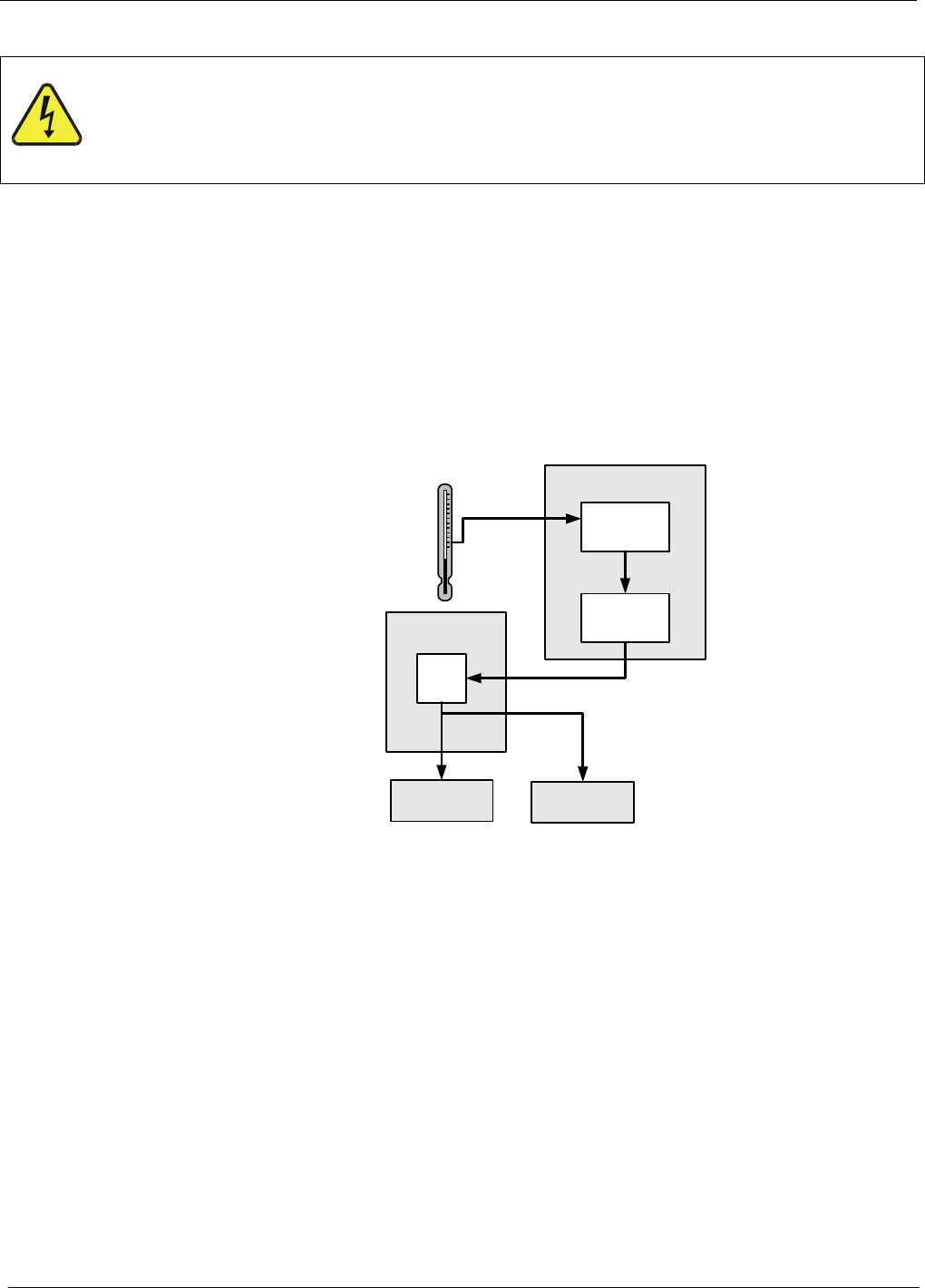
10.3.3.2. Heater Control
The relay PCA controls the various DC heaters related to the O
3
generator and
photometer options.
Thermistor(s)
(e.g. photometer sample gas temp.;
photometer UV lamp temp.; O
3
generator
lamp temp.; ect.)
RELAY PCA
DC
Control
Logic
MOTHERBOARD
A/D
Converter
(V/F)
CPU
O
3
Generator
Lamp Heater
PHOTOMETER
Lamp Heater
Figure 10-6: Heater Control Loop Block Diagram.
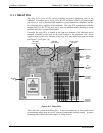
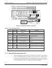
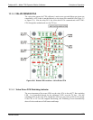
10.3.3.3. Relay PCA Status LEDs & Watch Dog Circuitry
Thirteen LEDs are located on the calibrator’s relay PCA to indicate the status of the
calibrator’s heating zones and some of its valves as well as a general operating watchdog
indicator. Table 10-1 shows the status of these LEDs and their respective functionality.
06873B DCN6388